


14 PTAC-SVX01C-EN
Installation
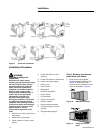
1. All units required either a power cord or hard wire kit to power the unit
2. The Hydronic chassis "W" ships with no electric heat
3. All Hydronic Chassis "W" units required a power cord
4. All 265volt Hydronic chassis "W" required subbase, fuses and socket.
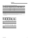
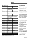
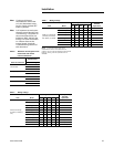
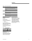
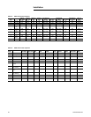
Table 5. Unit power supply
Voltage Options Accessory Accessory part number
115V
Option 1.
Required: Universal Power Cord 15
Amp
BAYPCRD007
A field supplied 115 volt 15 amp receptacle is mounted
in the building floor or wall. A Trane 115 volt 15 amp
power cord BAYPCRD007 is connected to the PTAC and
plugged into the receptacle.
Option 2.
Required: Universal Power Cord 15
Amp
BAYPCRD007
Universal Subbase BAYSUB001
A Trane subbase BAYSUB001 is attached to the wall
sleeve. A field supplied 115 volt 15 amp receptacle is
mounted into the subbase. A Trane 115 volt 15 amp
power cord BAYPCRD007 is connected to the PTAC and
plugged into the receptacle
Option 3. Required: Hard Wire Kit BAYHWRK001
Connector for Hardwire
Kit for 15 Amp
BAYCNHK031
A Trane hardwire kit BAYHRK001 is direct wired to the
building power supply and attached to the PTAC. A
Trane connector kit BAYCNHK031 is connected to the
PTAC and connected to the hard wire kit in the unit
mounted junction box
265 V
Option 1. Required: Universal Subbase BAYSUB001
Socket for subbase 20 or
30 Amp
BAYSCKT003, BAYSCKT004
Universal Power Cord
15,20 or 30 Amp
BAYPCRD004, BAYPCRD005,
BAYPCRD006
Fuses 15, 20 or 30 Amp BAYFUSE001, BAYFUSE002,
BAYFUSE003
Optional Power Switch BAYPSW002
Option 2. Required: Hard Wire Kit BAYHWRK001
Connector for Hardwire
Kit for 15, 20 or 30 Amp
BAYCNHK021, BAYCNHK022 ,
BAYCNHK023
Optional Power Switch if 30 Amp BAYPSW002
230/ 208 V
Option 1. Required: Universal Power Cord
15,20 or 30 Amp
BAYPCRD001, BAYPCRD002,
BAYPCRD003
Optional Power Switch BAYPSW002
Option 2. Required: Universal Subbase BAYSUB001
Socket for subbase 20
or 30 Amp
BAYSCKT001, BAYSCKT002
Universal Power Cord
15,20 or 30 Amp
BAYPCRD001, BAYPCRD002,
BAYPCRD003
Optional Circuit Breaker 15, 20 or
30 Amp
BAYCBKR001, BAYCBKR002,
BAYCBKR003
Power Switch BAYPSW002
Option 3. Required: Hard Wire Kit BAYHWRK001
Connector for Hardwire
Kit for 15, 20 or 30 Amp
BAYCNHK011, BAYCNHK012,
BAYCNHK013
Optional Power Switch BAYPSW002
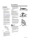
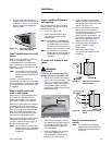
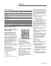
Step 7. Install the unit
controls.
The PTAC controller’s normal
operation can be operated by using
either
• Display module - can be wall-
mounted or unit mounted.
• Remote Class 2 thermostat -
For Remote Class 2 Thermostat
Installation, read installation,
operation, and maintenance booklet
carefully.
Look in Wiring Diagram section for
information on wiring.
If a remote thermostat is connected,
the unit's display will not be present
and the controller's normal space
temperature control functionality is
overridden by the remote device.
When the controller is being directed
by a remote thermostat, the
following inputs/functions are
disabled or not present:
1. User display inputs (setpoint/
mode/fan)
2. Dehumidification
3. Configuration setup (indoor fan,
setpoint limits, EMS offset,
display units)
4. Energy management system
5. Manual Test
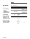
Unit functions that remain under
direct supervision of the controller
are:
1. Random Restart
2. Heat Pump OAT switchover
3. Tubing burst protection
4. Room freeze protection
5. Indoor coil freeze protection
6. Defrost control
When connected to a remote
thermostat, the controller interprets
the combination of thermostat inputs
as its operating mode and behaves
accordingly.
It is recommended to use a small
screwdriver to gently pryt the
removable treminal block "TB2" up
and off for easy connection.