


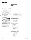


FIN-PRC004-EN60
Mechanical
Specifications
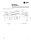
Recommended Schedule and Installation
Procedure
1.Layout job selecting enclosure lengths
with appropriate wall sleeve at each joint.
Space enclosures to suit. At end of run
use wall sleeve or 3” (76 mm) end to suit
job.
2.Layout pedestal bracket assembly so the
center-line is 7
1
/2” (191 mm) from each
end of enclosure to avoid interference
with enclosure gussets. Locate 1 pedestal
bracket assembly at center of enclosures
longer than 4 ft. (1.22 m).
NOTE: Schedule enclosures to overlap
accessories 1”-3” (25-76 mm) except ends
1”-2” (25-51 mm) with access door overlap
max. 1” (25 mm).
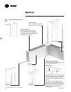
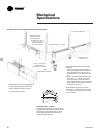
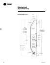
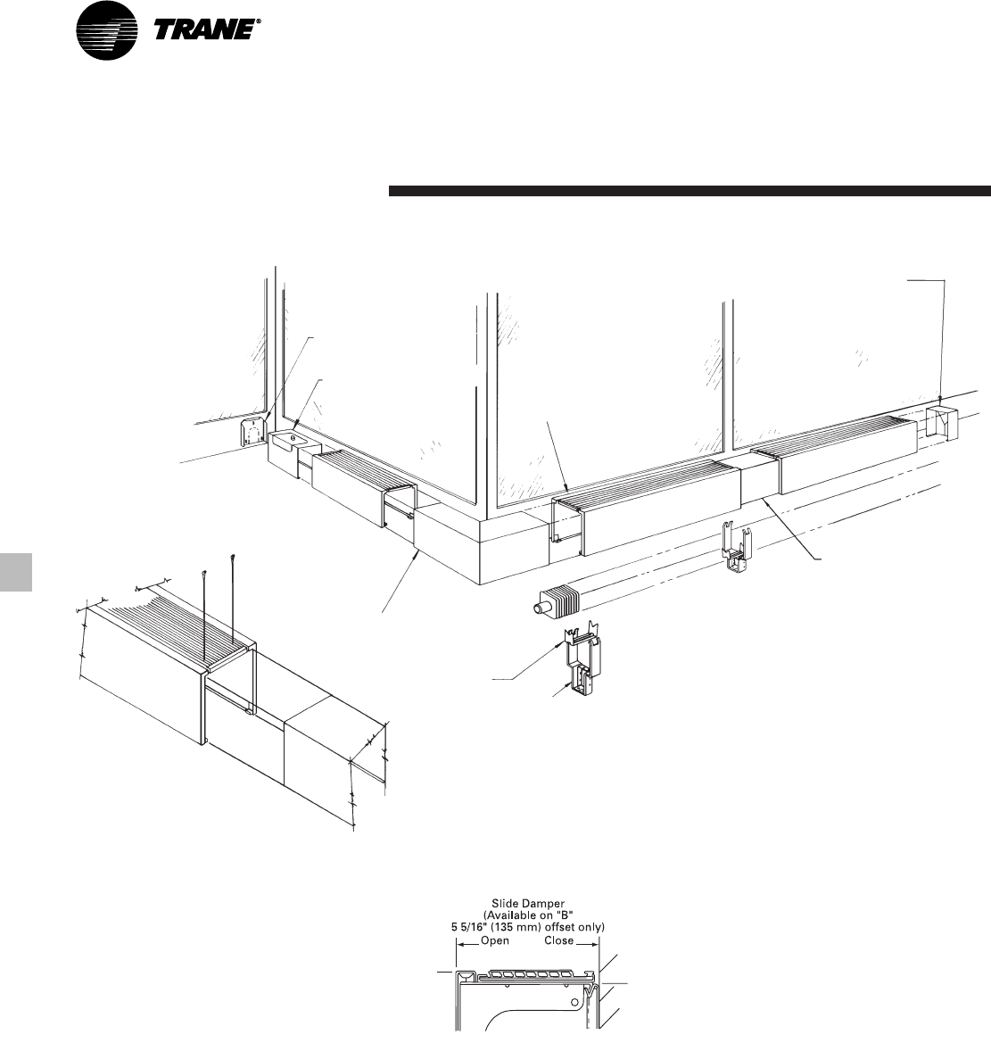
Slide Damper (SD) — Optional
The slide damper assembly consisting of two
integrated extruded aluminum clear anodized
grille plates provide air discharge control by
front to back positioning which requires no
mechanical actuating parts.
Note: Fasten accessory with 6 S.M. Screw
through solid part of grille. Drill 37 (104)
holes into accessory when in position.
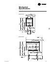
One wide enclosure shown.
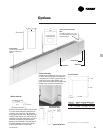
Installation Layout for Pedestal Mount E3A-1W One Wide Enclosure
Wall Sleeve Support
(Slotted For Piping
Where Specified)
Wall Sleeve 4” (102 mm)
or 8
3
/8” (213 mm)
(Access Door Optional
8
3
/8” (213 mm) Only)
Corner — Inside and/or
Outside Short Leg
Dimension 8
3
/8” (213 mm)
Cradle
Pedestal Bracket Assembly
Enclosure Assembly — Typical
3” (76 mm) End Assembly
Wall Sleeve in Run
At Each Joint