


FIN-PRC004-EN56
Mechanical
Specifications
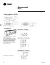
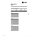
General
The contractor shall furnish and install
Trane wall fin as shown on the plans.
Ratings shall be IBR approved. Units
shall be installed in a neat and
workmanlike manner in accordance with
specifications and manufacturer
recommendations.
Heating Elements
Element types, as indicated on plans,
shall have integral fin collars which space
the fins and provide fin-to-tube surface
firmly bonded by mechanical expansion
of the tube to ensure durability, eliminate
noise from loose fins and assure
performance at cataloged ratings.
Elements shall be positively positioned
front-to-back, with provisions for silent
horizontal expansion and contraction.
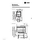
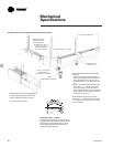
Enclosures
Enclosures shall be as scheduled on the
plans, constructed of 16-gauge 1.5 mm
thickness, or optional 14-gauge 1.9
thickness steel and shall mount into a
continuous roll-formed captive channel
mounting strip which permits hinge-type
mounting and access at the top and
invisible fastening onto rigidized, 14-
gauge (1.9 mm thickness) steel enclosure
brackets at the bottom. Enclosure
brackets shall be spaced at not more
than four-foot (1.2 m) intervals.
Front panels shall be individually
removable to facilitate cleaning, servicing
or replacement. All accessories shall
fasten to the enclosure assembly in a
manner which prevents contact with the
back wall during installation.
Cabinet air outlets of stamped sheet
metal or the manufacturer shall supply a
bar type extruded aluminum grille to
provide strong linear styling.
Type 3E and 4E enclosures shall be 16-
gauge (1.5 mm thickness) or 14-gauge
(1.9 mm thickness) steel. Type E3 and E3-
2W enclosures shall be 16-gauge steel.
Type X and CS enclosures shall be 18-
gauge (1.2 mm) steel with stamped
square outlet openings. Enclosures to
have smooth edges on all sides.
Pipe Enclosures
Pipe enclosures shall be as scheduled on
the plans, constructed of solid (16-gauge
1.5 mm thickness) steel or optional (14-
gauge 1.9 mm thickness) steel and shall
mount into a continuous roll-formed
captive channel mounting strip which
permits hinge-type mounting and access
at the top and fastening at the bottom
with visible fasteners by others. Front
panels shall be solid metal top and
bottom, one piece wrap around and be
individually removable to facilitate
servicing or replacement.
Standard Finish
All enclosures, mounting strips and
accessories are cleaned, phosphatized
and painted with one coat of prime,
baked enamel finish as standard.
Other Color Finishes
Other baked-on enamel color finishes
available as standard shall be chosen
from Color Selection Chart UNT-S-10.
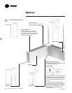
Accessories And Options
End panels, inside and outside corners
and enclosure extensions shall be die-
formed and shall lock to enclosure
assembly without visible fasteners.
Dampers (hydronic units only) shall
reduce heating capacity up to 70 percent
when closed and shall be factory
mounted on the element. The control
dial shall be jam-proof and have a
mechanism which prevents damage to
the dial or damper. As an alternate, the
contractor shall furnish and install control
valves and appropriate access.
Access panels shall be installed where
valves, balancing cocks or traps are
indicated on the plans.
The 3E and 4E wall mounted element
covers (16-gauge (1.5 mm thickness) or
14-gauge (1.9 mm thickness) steel) and
accessories shall be provided as
indicated on the plans. (Accessories
require visible fasteners.)
Type E3 and E3-2W three-sided pedestal
mounted element covers and
accessories shall be provided where
shown on plan. (Enclosures of 16-gauge
(1.5 mm) steel only.) (Accessories require
visible fasteners.)
Back panels, sill extensions, mullion
channel, stamped sheet metal, front air
inlet grilles, tamperproof screw
assemblies and pilaster covers shall be
provided where indicated on plans. To
prevent dirt streaking, contractor shall
either apply dirt guard gasket to
mounting strip or caulk along top of
mounting strip.
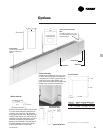
Bottom Air Inlet Grille
The bottom air inlet grille shall be of
stamped sheet metal and part of the
front panel (one piece) installs into the
mounting strip at the top and attaches to
the wall at the bottom with visible
fasteners by others. Bottom air inlet grille
configurations use Type E wall brackets
for installation of the heating element.