FIN-PRC004-EN64
Mechanical
Specifications
Type DS Double Slope
Wall Mounted
Specifications
Natural convection double slope wall
mounted. Wall fin shall be furnished to
meet the specified capacity. Enclosures
etc., heating elements and accessories
shall be installed in accordance with the
manufacture’s recommendations.
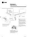
TYPE - DS - Double Slope Enclosure
Mounting
Hydronic Type DS Double Slope Wall Fin
enclosures shall be wall mounted 40”
(1016 mm) minimum above the floor
level to obtain catalog capacities.
Type DS double slope enclosure
furnished with louvered air inlet and
outlet grilles of one piece full wrap-
around design for complete
engagement with the wall to prevent
access to the inside of the enclosure.
Enclosures fabricated from 16 gauge (1.5
mm thickness) steel for strength and
durability. Optional 18 gauge (1.2 mm
thickness) steel is available. All enclosure
panels manufactured with interlocking
slip joints provides a positive snap fit
between enclosures. Internal 14 gauge
(1.9 mm) gussets provide additional
strength and rigidity. A full back plate
(one piece) is furnished with a formed
mounting channel at the top of the back
plate for installation of the element
brackets which are mounted to the top
inside form of the back plate providing
proper positioning of each bracket and
engages the top of the enclosure. The
enclosures air inlet are provided with a
7
/16” (11 mm) 90 degree turn down for
fastening the bottom of the enclosure
panel to the bottom form of the
backplate to securely lock it in place.
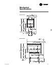
Enclosure depth of 5
5
/16” (135 mm)
furnished in heights of 19
1
/2” (495 mm),
25
1
/2” (648 mm) and 29
1
/2” (749 mm).
Enclosures available in 2 feet (0.61 m)
through 8 feet (2.4 m) in 6” (0.15 m)
increments.
Enclosure brackets with adjustable
element supports are die-formed
channel type construction to provide
rigid support of the heating element.
Nickel chromium plated ball bearings
encased in a nylon insert with galvanized
element cradles provides for silent glide
operation during expansion and
contraction of the heating element.
Dampers
Fully modulating knob operated and
tamper resistant dampers field installed
on the air inlet grille and gussets for
positive temperature control.
Accessories
End caps 3” (76 mm) wide in left and
right hand configurations.
End caps 8
3
/8” (213 mm) wide with
access door in left and right hand
configurations.
4” (102 mm) and 8
3
/8” (213 mm) wide
wall sleeves.
8
3
/8” (213 mm) wide wall sleeve with
access door.
90 degree inside and outside corners.
All accessories die-formed with flange at
top to engage behind the back plate.


