


FIN-PRC004-EN12
Selection
Procedure
For headered two-row element
installations (elements piped in parallel),
the maximum capacity from Table S-6 can
be doubled.
For water temperature drop other than
20°F (-6.7C), the maximum capacity may
be determined as follows:
Maximum Capacity =
Max. Cap. (Table S-6) x Actual Temp. Drop
20°F Temp. Drop
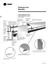
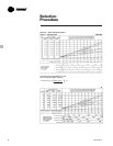
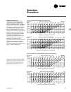
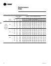
Maximum Installed Lengths
Hot water systems velocity and pressure
drop are two factors that will influence
the maximum installed lengths of wall fin
hot water systems. Velocity in any pipe
size is dependent upon the capacity of
the installed wall fin and the water
temperature drop through the unit. Table
S-6 gives the maximum installed
capacity for any single wall fin unit or
loop based on *5 ft./sec (1.5 m/sec).
velocity through the tube (maximum
recommended for quiet operation) and a
20°F (-6.7°C) water temperature drop.
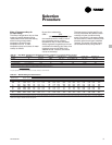
The maximum recommended installed
length for any element and enclosure
combination can be determined by
dividing the maximum recommended
capacity from Table S-6 by the lineal foot
capacity of the element and enclosure
combination from the capacity table.
Wall fin elements having the smallest
tube sizes and highest velocities will give
the most efficient heat output and the
lowest pipe fitting costs. However, this
should be balanced against lower
pressure drops and perhaps a more
economical circulating pump selection
made possible with large tube sizes or
larger temperature drops.
*Tables based on 3 ft/sec. (.91 m/sec.)
velocity should not exceed 8 ft/sec
(2.4 m/sec.) due to pipe corrosion.
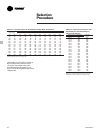
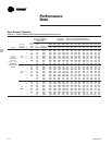
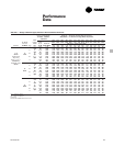
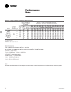
Table S-6 — Hot Water Systems, Maximum Capacity*
Tube Size 1
1
/4” Steel 2” Steel 1
1
/4” Copper 1” Copper
3
/4” Copper
Maximum (32 mm) (51 mm) (32 mm) (25 mm) (19 mm)
Capacity
(Btu Hr.) 240,000 530,000 210,300 140,800 85,500
(Watts) 70,344 155,343 61,639 41,268 25,060
*For low pressure systems. Based on
1
/4 psi (1.7kPa) pressure drop per 100 feet (30.5 m).