


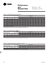
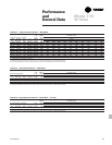

91FIN-PRC004-EN
Mechanical
Specifications
Security
Enclosures
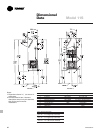
Models S and F
Specifications
Natural convection security wall fin shall
be furnished to meet the specified
capacity. Enclosure, heating elements
and accessories shall be installed in
accordance with the manufacturer’s
recommendations. All enclosures shall
be tamper-resistant.
Mounting
Hydronic security slope top and flat top
wall fin enclosures shall be wall-
mounted 3
1
/2” (89 mm) to 4” (102 mm)
above the floor level to obtain catalog
capacities.
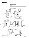
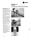
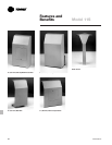
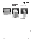
Enclosures
Type S — Slope top outlet and Type F —
flat top outlet: Each enclosure top/front/
bottom panel shall be of one piece (full
wrap-around design) for complete
engagement with the wall to prevent
access to the inside of the unit.
Enclosures shall be fabricated from 14-
gauge (1.9 mm thickness) steel for
strength and durability. Optional 12-
gauge (2.6 mm thickness) steel shall be
available. All enclosure panels shall be
manufactured with
1
/8” (3 mm) diameter
holes on
3
/16” (5 mm) staggered centers
for a partial perforated (inlet and outlet)
panel with internal interlocking slip joints.
Optional fully perforated enclosures of
the entire panel shall be available with
intermediate overlapping wall sleeve
with pre-punched fastener holes for
panel-to-panel alignment and fastening.
Cabinet depth shall be 5
5
/16” (135 mm)
for 12” (305 mm) high enclosures for
single tier element and 18” (457 mm)
enclosures for single or double tier
element applications. Enclosures shall
be available in 2-feet (.61 m) through
8- feet (2.4 m) in 6” (.15 m) increments.
•
Partially Perforated — 14-Gauge
(Standard)
•
Partially Perforated — 12-Gauge
(Optional)
•
Fully Perforated — 14-Gauge
(Optional)
•
Fully Perforated — 12-Gauge
(Optional)
Enclosure Suspension System
Enclosures with (visible tamper- resistant
fasteners by others) for heating elements
shall be installed to a continuous partial
back plate/mounting strip manufactured
from 14-gauge (1.9 mm thickness) steel
at the top with the bottom of the front
panel fastened to the wall. Optional
continuous full back plate/mounting strip
manufactured from 14-gauge (1.9 mm
thickness) steel shall be available.
Elements or return and supply piping
shall be secured to the wall with wall
type element brackets manufactured of
14-gauge (1.9 mm thickness) Galvanneal
steel with channel formed edges for
rigidity. Each wall bracket shall be
furnished with galvanized element
cradles, nylon inserts with snap in rust
resistant nickel-chromium plated ball
bearings for silent glide operation of the
heating element.
•
Partial back plate/mounting strip
(Standard)
•
Full back plate/mounting strip
(Optional)
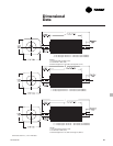
Accessories
— End caps left and right hand
configurations,
— End Trims 6” (152 mm) wide shall
have wrap around design less
fastener holes,
— 90 degree inside corners and
— 90 degree outside corners
— All accessories shall be manufactured
from 14-gauge (1.9 thickness) steel to
provide a maximum security
installation.
Color Finish
All enclosures, back plate/mounting strip
and accessories shall be painted with a
baked-on commercial primer paint as
standard. Optional baked-on enamel
color finishes shall be available.
Color Options
Baked-on enamel color finish shall be
chosen from Color Selection Chart UNT-
S-10.
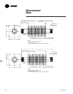
Heating Elements
•
3
/4” CA (19 mm)
(Copper Tube-Aluminum Fin)
The heating elements shall be
constructed of seamless copper
tubing mechanically expanded into
aluminum fins. One tube end swaged
for end-to- end joining. 4
1
/4” x 3
5
/8”
(108 mm x 92 mm) size fins x .020”
(.51 mm) fin thickness for maximum
heat transfer.
— Fin spacing of 40 fins per foot
(131 fins per m).
— Fin spacing of 50 fins per foot
(164 fins per m).