


Installation
CAH-SVX01A-EN 37
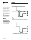
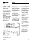
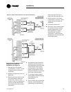
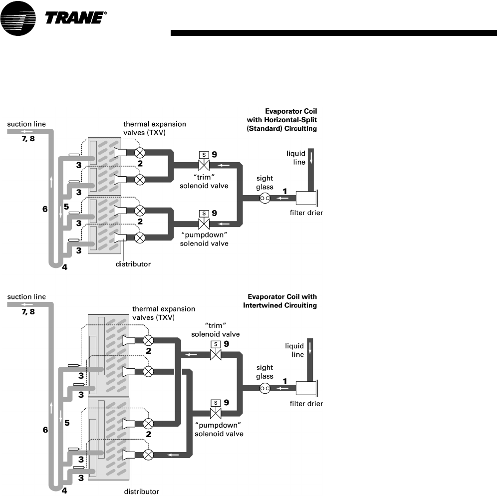
Single-Circuit Condensing Units:
Evaporator Coil with Four
Distributors (see Figure 37)
1 Pitch the liquid line slightly—
1 inch/10 feet [1 cm/3 m]—so the
refrigerant drains toward the
evaporator.
2 Provide one expansion valve per
distributor.
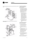
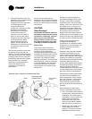
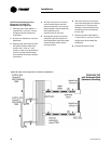
3 Slightly pitch the outlet line from
the suction header toward the
suction riser—that is, 1 inch/
10 feet [1 cm/3 m] in the direction
of flow. Use the tube diameter
that matches the suction-header
connection.
Figure 37. Single-circuit evaporator coil with four distributors
4 Arrange the suction line so the
refrigerant gas leaving the coil
flows downward, past the lowest
suction-header outlet, before
turning upward. Use a double-
elbow configuration to isolate
the thermal expansion valve bulb
from other suction headers.
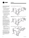
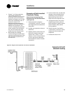
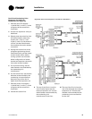
5 For horizontal tubing, use the
tube diameter recommended by
the condensing unit
manufacturer.
6 For the vertical riser, use the tube
diameter recommended by the
condensing unit manufacturer.
Assure the top of the riser is
higher than the evaporator coil.
7 Pitch the suction line slightly—
1 inch/10 feet [1 cm/3 m]—so the
refrigerant drains toward the
evaporator.
8 Insulate the suction line.
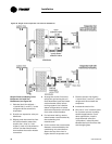
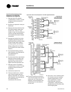
9 Only use a “trim” solenoid valve
for constant-volume, humidity-
sensitive applications. For all
other applications, install a
single solenoid valve (the
“pumpdown” solenoid valve)
between the liquid-line filter drier
and the sight glass.