Installation
24 CAH-SVX01A-EN
Duct Connections
All duct connections to the units
should be installed in accordance
with the standards of the National
Fire Protection Association (NFPA)
for selecting and installing of air
conditioning and ventilating
systems other than residence type
(NFPA 90A), and residence type
warm air heating and air
conditioning systems (NFPA 90B).
To ensure the highest fan efficiency,
duct turns and transitions must be
made carefully, minimizing air
friction losses and turbulence.
Proper duct work installation by such
organizations as SMACNA (Sheet
Metal and Air Conditioning
Contractors National Association,
Inc.) should be adhered to.
Component
Installation
Requirements
Each component in the Custom air
handler may have installation
requirements that could affect the
unit’s performance.
Note: For components included in
the unit but not included in this
manual, reference the component
manufacturers specific Installation,
Maintenance, and Operation
manual. Copies of these manuals
are either included in the package
with this unit IOM or are attached to
the components mounted in the
unit.
Fans
The fan and motor assembly are
internally isolated. The fan and
motor bases are bolted to a
minimum of four spring isolators.
The isolators are secured to the fan
section support base. Shipping tie-
down blocks are bolted to the
isolators between the fan base and
the isolator support frame.
To activate the isolation, remove the
shipping tie-down blocks. Retain
these blocks for use in adjusting
isolators if necessary.
Isolator Adjustment
Note: Isolators are pre-adjusted and
set at the factory. Follow this
procedure only if necessary and as it
applies to the isolators used in this
unit. This procedure, for isolators
can, and should be, performed by
one person to ensure that the proper
sequence is followed.
Isolators are selected for distribution
of equipment weight, but may not all
compress the same. This procedure
assumes the base surface is level.
Isolators are not intended to be
leveling devices.
1 Verify that the shipping bolts that
hold the fan base in a fixed
position have been removed.
2 Remove the jam nut on top of the
isolator adjusting stud at the first
isolator to be adjusted. Check
that the shipping block is in
place.
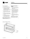
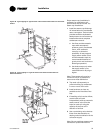
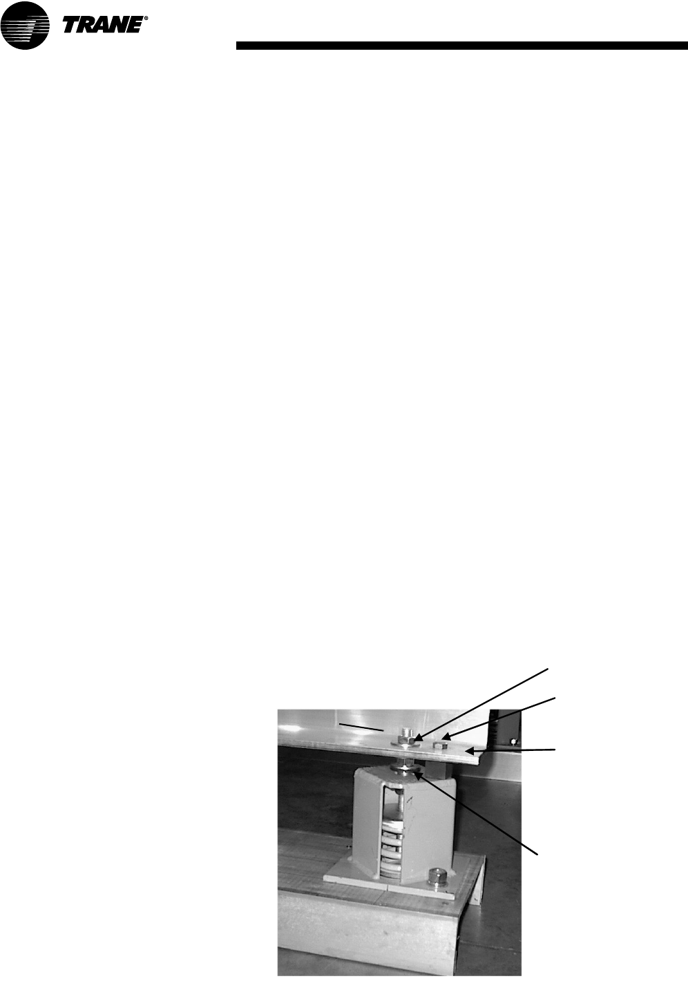
Figure 19. Isolator
SHIPPING TIE-
DOWN BLOCK
(SHIM)
ADJUSTING
NUT
JAM NUT
SHIPPING
BOLT
FAN BASE
ƽ WARNING
Hazardous Voltage with
Capacitors!
Disconnect all electric power,
including remote disconnects and
discharge all motor start/run
capacitors before servicing. Follow
proper lockout/tagout procedures to
ensure the power cannot be
inadvertently energized. For variable
frequency drives or other energy
storing components provided by
Trane or others, refer to the
appropriate manufacturer’s
literature for allowable waiting
periods for discharge of capacitors.
Verify with an appropriate voltmeter
that all capacitors have discharged.
Failure to disconnect power and
discharge capacitors before
servicing could result in death or
serious injury.
Note: For additional information
regarding the safe discharge of
capacitors, see PROD-SVB06A-EN.
Turn the adjusting nut 2 or 3 turns
only, counterclockwise on each
isolator in a sequenced manner. The
equipment weight will compress the
spring inside the housing
approximately 1/4 inch.


