


Installation
12 CAH-SVX01A-EN
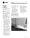
TCP Model
Assembly
Instructions
If your nameplate model number
begins with TCP, use the assembly
instructions below.
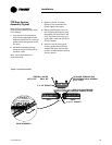
Joining Sections Edge-to-
Edge
Units must be installed level for
proper drainage of condensate from
the drain pan. In addition, each
section in a multi-section unit must
be properly supported.
Note: Leveling each section,
beginning with the first, is critical.
Failure to level and align the
sections immediately creates greater
misalignment or even structural
damage afterward.
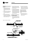
1 Remove all crating and wrapping
from the surfaces to be joined.
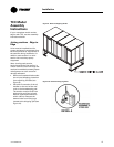
2 Place one section of the air
handler into the desired position.
Verify each section is level and
properly supported prior to
proceeding with assembly. Each
unit must be level side-to-side
and front to back. Check
squareness measuring the
critical dimensions given.
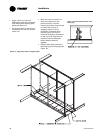
3 When the unit is positioned and
squareness is assured within 1/8-
inch, remove all lifting lugs
located along the split plane.
4 Install 4-inch x 1/4-inch neoprene
gasket to all mating surfaces of
the section, including the internal
walls. This gasket must be
applied to the full perimeter of
the section split of both sections
to be joined.
5 Move the next mating section
into alignment with the
positioned section. Alignment of
sections must be completed
before gasket surfaces meet. The
two sections should be within 12
inches to reduce the amount of
dragging required.
6 Remove lifting lugs on mating
section as required.
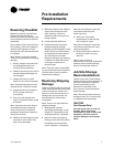
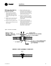
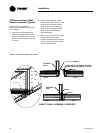
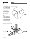
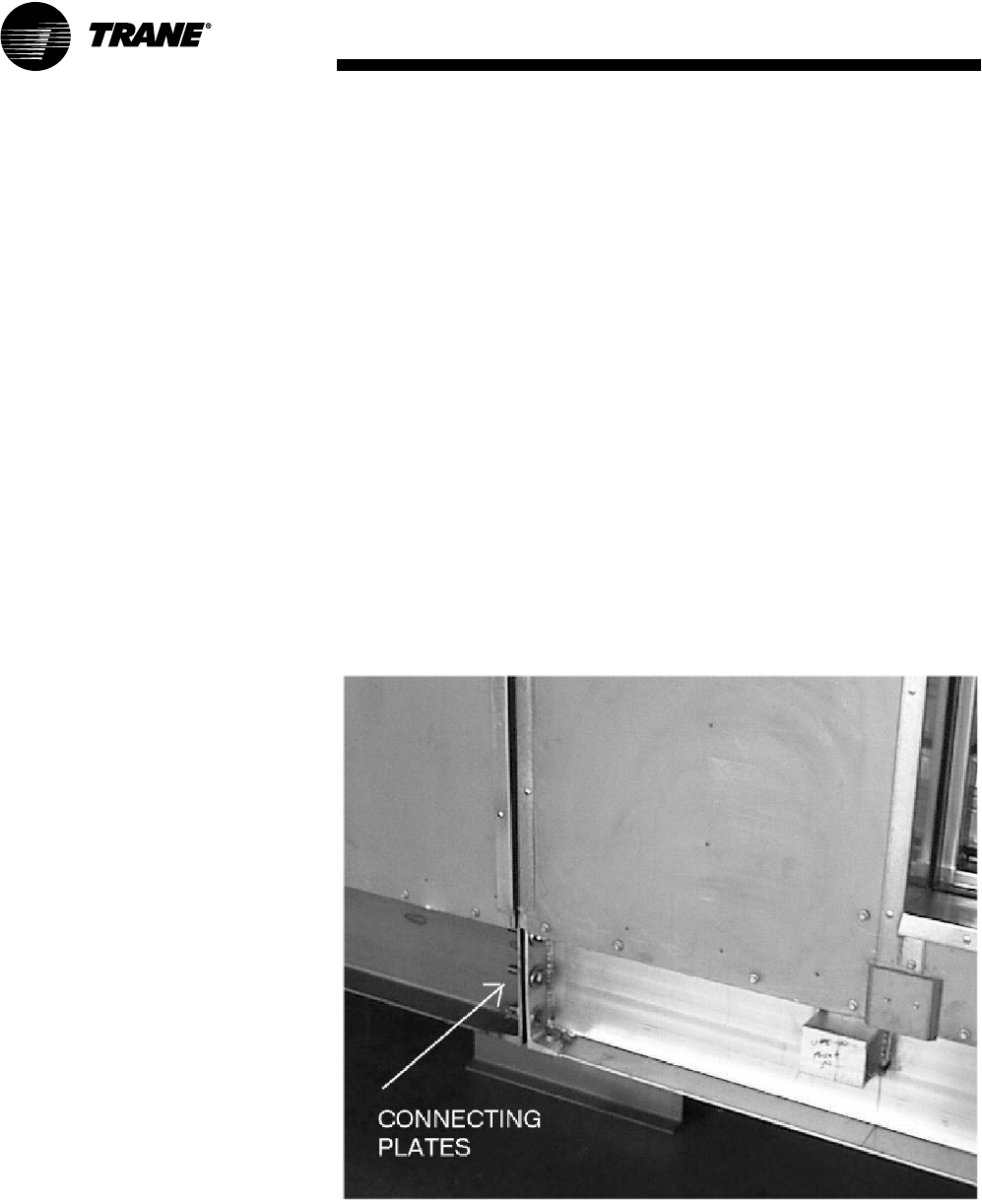
7 Insert threaded rods through
each hole of each mating
connecting plate (see Figure 4).
Bring each connecting surface
together uniformly until
gasketing is contacted.
Note: Use field provided threaded
rods inserted in all holes of each
connecting plate to prevent damage
and distortion of the sections as they
are joined. Tighten all rods in
sequence. Do not try to join sections
by tightening only some of the rods.
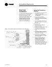
Figure 4. Insert threaded rods through each hole of mating connecting plate.
Note: Failure to compress the
gasketing may result in air leakage.
8 Secure the unit sections at the
base using the field provided
bolts, nuts and washers at the
connecting plates.
9 Once the sections are pulled
together, install the assembly
hardware as applicable for the
walls, roof, and the base as
demonstrated in the following
assembly sections.