


– 66 –
11. HOW TO DIAGNOSE THE TROUBLE
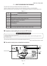
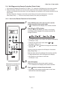
The pulse motor circuits are mounted to both indoor and outdoor units.
Therefore, diagnose troubles according to the trouble diagnosis procedure as described below.
(Refer to the check points in servicing written on the wiring diagrams attached to the indoor/outdoor units.)
Table 11-1
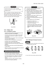
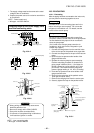
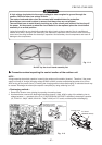
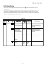
Precautions when handling the new inverter (3DV Inverter)
CAUTION: HIGH VOLTAGEN
The high voltage circuit is incorporated.
Be careful to do the check service, as the electric shock may be caused in case of touching parts on the
P.C. board by hand.
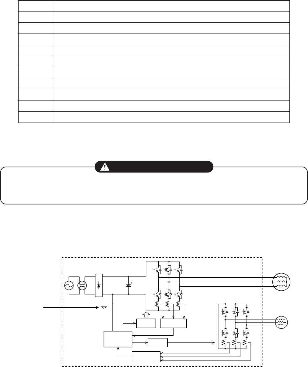
The new inverter (3DV inverter) will be incorporated starting with this unit.
(3DV: 3-shunt Discrete Vector control)
The control circuitry has an uninsulated construction.
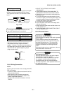
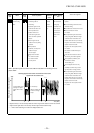
Fig. 11-1
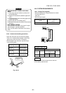
IGBT × 6
FET × 6
MCU
Compressor
Fan motor
Shared potential
Driver
Driver
Amplifier
Amplifier
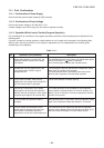
No.
1
2
3
4
5
6
7
8
9
10
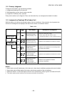
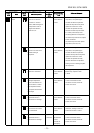
Troubleshooting Procedure
First Confirmation
Primary Judgment
Judgment by Flashing LED of Indoor Unit
Self-Diagnosis by Remote Controller (Check Code)
Judgment of Trouble by Every Symptom
Check Code 18 and 1E
Troubleshooting
How to Diagnose Trouble in Outdoor Unit
How to Check Simply the Main Parts
How to Simply Judge Whether Outdoor Fan Motor is Good or Bad
FILE NO. SVM-10020