– 101 –
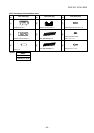
No.
Part name
Control board
assembly
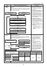
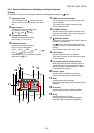
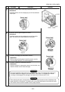
Procedure
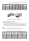
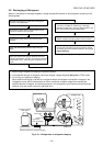
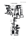
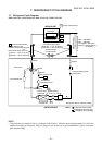
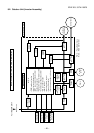
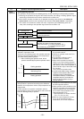
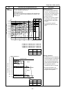
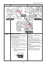
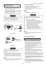
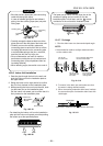
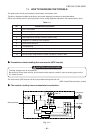
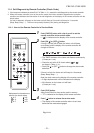
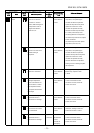
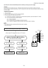
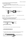
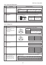
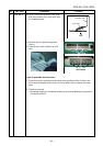
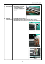
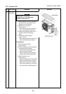
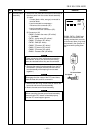
1. Disconnect the leads and connectors connected to
the other parts from the control board assembly.
1) Leads
• 3 leads (black, white, orange) connected to
terminal block.
• Lead connected to compressor :
Disconnect the connector (3P).
• Lead connected to reactor :
Disconnect the two connectors (2P).
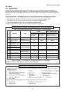
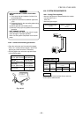
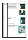
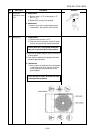
2) Connectors (×8)
CN300 : Outdoor fan motor (3P: white)*
(* : See Note)
CN701 : 4-way valve (2P: yellow)*
CN600 : TE sensor (2P: white)*
CN700 : PMV (6P: white)
CN603 : TS sensor (3P: white)*
CN601 :TD sensor (3P: white)*
CN602 : TO sensor (2P: white)
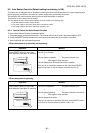
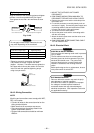
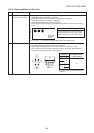
NOTE
These connectors have a disconnect prevention
mechanism: as such, the lock on their housing
must be released before they are disconnected.
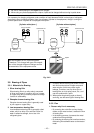
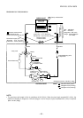
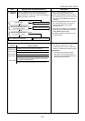
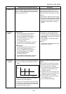
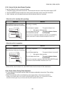
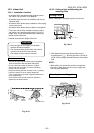
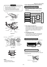
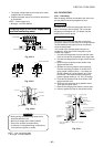
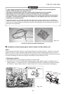
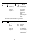
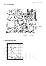
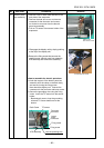
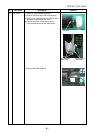
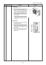
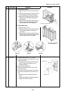
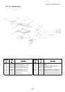
2. Remove the control board assembly from the P.C.
board base. (Remove the heat sink and control
board assembly while keeping them screwed
together.)
NOTE
Disengage the four claws of the P.C. board base,
hold the heat sink, and lift to remove it.
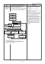
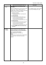
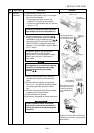
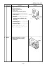
3. Remove the two fixing screws used to secure the
heat sink and control board assembly.
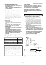
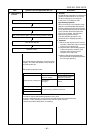
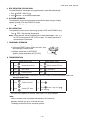
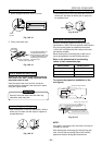
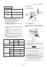
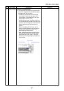
4. Mount the new control board assembly.
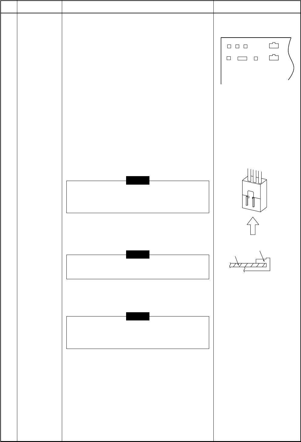
NOTE
When mounting the new control board assembly,
ensure that the P.C. board is inserted properly
into the P.C. board support groove.
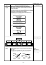
CN300, CN701, CN600 and
CN603 are connectors with
locking mechanisms: as such,
to disconnect them, they must
be pressed in the direction of
the arrow while pulling them
out.
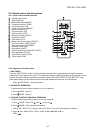
P.C. board base
P.C. board
CN700 CN602
CN300
CN701
CN603
CN601
CN600
FILE NO. SVM-10020
Remarks
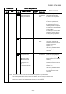
CN500
CN500 : Pressure SW. (2P:white)