


– 56 –
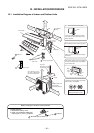
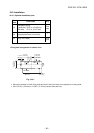
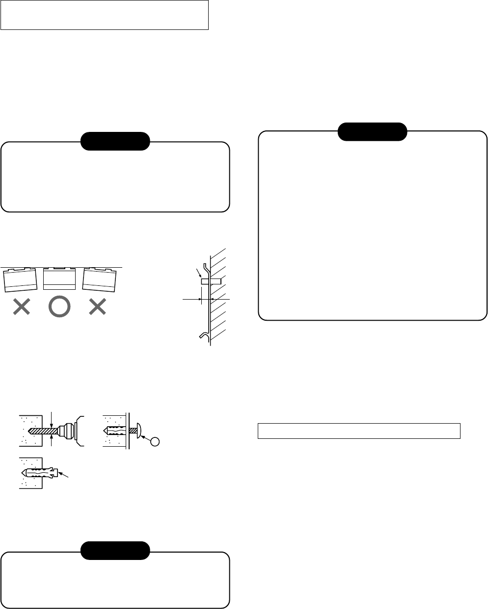
When the installation plate is directly
mounted on the wall
1. Securely fit the installation plate onto the wall by
screws with the upper and lower catches, that
hold the indoor unit, facing out.
2. To mount the installation plate on a concrete wall
use anchor bolts. Drill the anchor bolt holes as
illustrated in the above figure.
3. Install the installation plate horizontally and level.
CAUTION
When installing the mounting plate with mounting
screw, do not use the anchor bolt hole.
Otherwise, the unit may fall down and result in
personal injury and property damage.
Fig. 10-3-4
Fig. 10-3-5
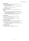
CAUTION
Failure to firmly install the unit may result in
personal injury and property damage if the
unit falls.
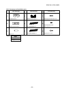
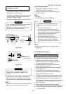
• In case of block, brick, concrete or similar type
walls, make 3/16 in. (5 mm) dia. holes in the wall.
• Insert clip anchors for appropriate mounting screws
NOTE :
• Secure four corners and lower parts of the mounting
plate with 4 to 6 mounting screws to install it.
Anchor bolt
Projection
9/16 in. (15 mm)
3/16 in3 (5 mm) dia. hole
Clip anchor
(local parts)
7 Mounting screw
Ø5/32 in. x 1 in.
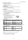
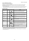
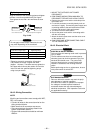
10-3-3. Electrical Work
1. The supply voltage must be the same as the
rated voltage of the air conditioner.
2. Prepare a power source for the exclusive use of
the air conditioner.
NOTE :
• Wire type :
Power supply cord minimum AWG 14.
CAUTION
• This appliance can be connected to a main
circuit breaker in either of the following two
ways.
1. Connection to fixed wiring:
A switch or circuit breaker which discon-
nects all poles and has a contact separa
tion
of at least 1/8 in. (3 mm) must be incorporated
in the fixed wiring. An approved circuit
breaker or switch must be used.
2. Connection with power supply plug:
Attach power supply plug with power cord
and plug it into wall outlet. An approved
power supply cord and plug must be used.
NOTE :
• Perform wiring work being sure the wire length is
long enough.
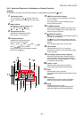
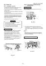
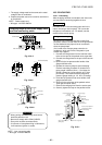
How to connect the connecting cable
Installation plate
(Keep horizontal direction.)
or less
(
∅
4 mm x 25 mm)
.
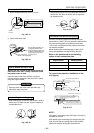
1. Open the air inlet grille upward.
2. Remove the screws securing the front panel.
3. Slightly open the lower part of the front panel,
then pull the upper part of the front panel toward
you to remove it from the rear plate.
4. Insert the condit pipe (according to the local rule)
into the pipe hole on the wall.
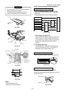
5. Remove the conduit mount by loosening the fixing
screw. (Fig. 10-3-
7
)
6
. Fix conduit pipe to conduit mount with lock nut.
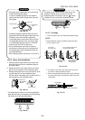
7. Pull out the connecting wire through the conduit pipe
and process the wire. (Fig. 10-3-
8
)
8. Take out the wire to the front and fix it to the terminal
block. Be careful not to make mis-wiring (Fig. 10-3-
9
)
9. Firmly tighten the terminal screws to prevent them
from loosening. Tightening torque: 0.9 lbf. ft (1.2 N·m).
After tightening, pull the wires lightly to confirm that
they of not move.
10. Secure the connecting wire with the cord clamp.
11. Fix the conduit mount back to the body by fixing a screw.
12. Fix the front panel, terminal cover and air inlet grille
on the indoor unit.
10-3-4. Wiring Connection
FILE NO. SVM-10020