


.
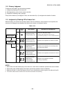
Gas side
Ø1/2 in. (Ø12.70 mm)
37 to 46 lbf.ft
(50 to 62 N·m)
Gas side
Ø3/8 in. (Ø9.52 mm)
24 to 31 lbf.ft
(33 to 42 N·m)
Liquid side
Ø1/4 in. (Ø6.35 mm)
10 to 13 lbf.ft
(14 to 18 N·m)
Service port
10 to 13 lbf.ft
(14 to 18 N·m)
Hexagon wrench
is required.
3/16
in.
(4
m
m
•
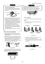
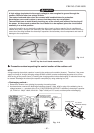
KEEP IMPORTANT 5 POINTS FOR PIPING
WORK.
(1) Take away dust and moisture (inside of the
connecting pipes).
(2) Tighten the connections (between pipes and
unit).
(3) Evacuate the air in the connecting pipes using
a VACUUM PUMP.
(4) Check gas leak (connected points).
(5) Be sure to fully open the packed valves before
operation.
•
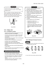
UNIT DAMAGE HAZARD
Failure to follow this caution may result in equip-
ment damage or improper operation.
Never use the system compressor as a vacuum
pump.
CAUTION
FILE NO. SVM-10020
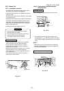
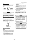
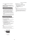
10-5-2. Packed valve handling precautions
• Open the valve stem until it touches the stopper.
Once it is in contact with the stopper, refrain form
applying any more force than is necessary.
• Securely tighten the valve stem cap with torque
in the following table:
Fig. 10-5-2
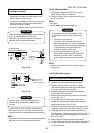
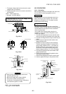
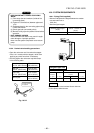
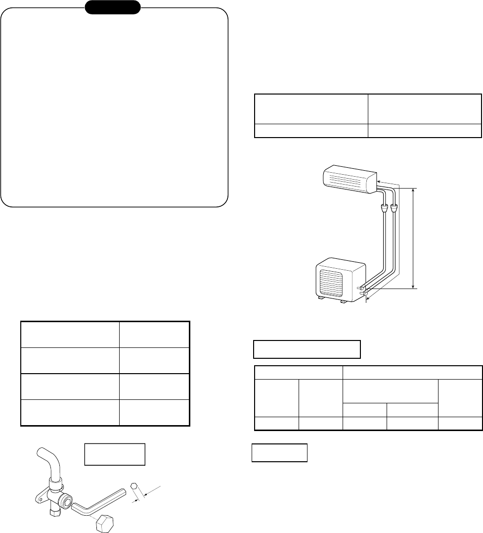
10-6. SYSTEM REQUIREMENTS
• Minimum refrigerant line length between the outdoor
unit and indoor unit is
6.6ft. (2m).
•
Maximum pipe lengths
Allowable Pipe length T
(ft (m))
Height difference
(ft (m))
66 (20) 33 (10)
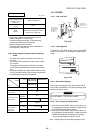
Refrigerant pipe sizes
HT
Liquid side Gas side
Outer
Diameter
In. (mm)
Thickness
In. (mm)
Outer diameter
In. (mm)
Thickness
In. (mm)
(09, 12LKV) (15, 17, 22LKV)
Ø1/4 (6.35) 0.03 (0.8) Ø3/8 (9.52) Ø1/2 (12.70) 0.03 (0.8)
Both lines need to be insulated. Use a minimum
5/16 in (8mm) wall thickness.
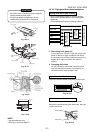
10-6-1. Piping (Field supplied)
(Indoor − Outdoor H)
Insulation
– 63 –