


– 57 –
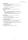
CAUTION
• Be sure to refer to the wiring system diagram
labeled inside the front panel.
• Check local electrical regulations for any
specific wiring instructions or limitations.
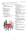
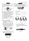
10-3-5. Piping and Drain Hose Installation
Piping and drain hose forming
• Since condensation results in machine trouble,
make sure to insulate both the connecting pipes
separately.
(Use polyethylene foam as insulating material.)
NOTE :
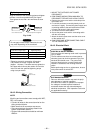
• Use stranded wire only.
• Wire type : minimum AWG14
Fig. 10-3-10
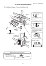
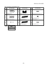
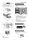
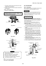
1. Die-cutting front panel slit
Cut out the slit on the left or right side of the front
panel for the left or right connection and the slit
on the bottom left or side of thefront panel for the
bottom left or right connection with a pair of
nippers.
2. Changing drain hose
For left connection, left-bottom connection and
rear-left connection’s piping, it is necessary to
relocate the drain hose and drain cap.
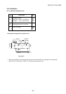
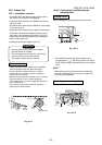
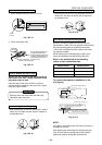
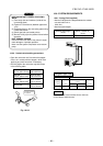
CAUTION
How to remove the drain cap
Clip drain cap with needle-nose pliers, and pull out.
Fig. 10-3-11
How to remove the drain hose
The drain hose is secured in place by a screw.
Remove the screw securing the drain hose, then pull
out the drain hose.
Die-cutting
Front panel slit
Changing
drain hose
Piping preparation
Rear right
Rear left
Bottom left
Left
Bottom right
Right
3
1
2
Air inlet grille
Front panel
S
L2
L1
Ground
line
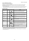
4-5/16 in. (110 mm)
3-5/32 in. (80 mm)
13/16 in. (20 mm)
3/8 in. (10 mm)
Fig. 10-3-9
Fig. 10-3-6
Fig. 10-3-7
Fig. 10-3-8
FILE NO. SVM-10020
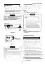
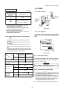
Conduit mount
Fixing screw
Conduit pipe
Lock nut
Inter connecting
cable
Heat insulator
Drain hose
Fig. 10-3-12