


– 51 –
10. INSTALLATION PROCEDURE
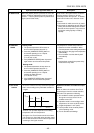
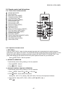
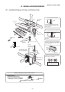
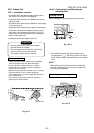
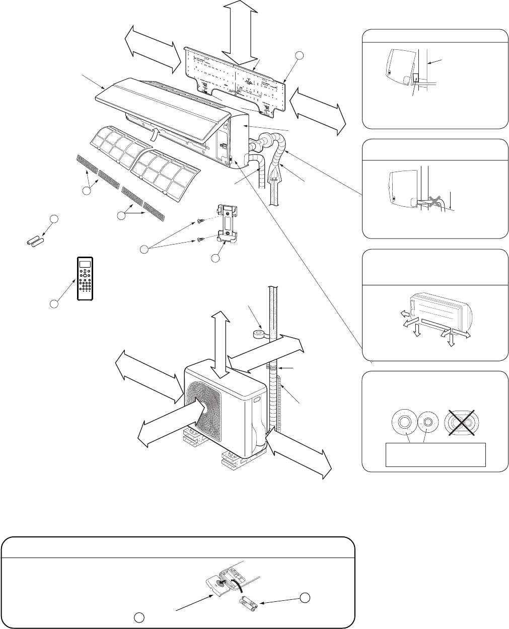
10-1. Installation Diagram of Indoor and Outdoor Units
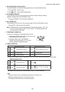
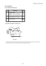
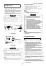
Before installing the wireless remote controller
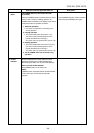
• Loading Batteries
1. Remove the battery cover.
2. Insert 2 new batteries (AAA type)
following the (+) and (
−
) positions.
3 Batteries
2 Wireless remote controller
A
C
L
FILE NO. SVM-10020
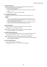
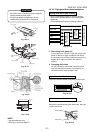
Insulate the refrigerant pipes separately
with insulation, not together.
2
3
8
4
Insert the cushion between the indoor
unit and wall, and tilt the indoor unit for
better operation.
For the rear left and left piping
Wall
Make sure to run the drain hose sloped
downward.
Do not allow the drain hose to get slack.
Cut the piping
hole sloped
slightly.
The auxiliary piping can be connected to
the left, rear left, rear right, right, bottom
right or bottom left.
Right
Rear
right
Bottom
right
Rear
left
Bottom left
Left
5/16 in. (8 mm) thick heat
resisting polyethylene foam
1
Batteries
Pan head
wood screw
Remote control holder
Vinyl tape
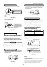
Apply after carrying
out a drainage test.
Wireless remote control
Saddle
Extension drain hose
(Not available,
provided by installer)
Shield pipe
(
A
t
t
a
c
h
t
o
t
h
e
f
r
o
n
t
p
a
n
e
l
.
)
A
i
r
f
i
l
t
e
r
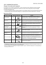
Installation
plate
2-9/16 in. (65 mm)
or more
7
i
n
.
(
1
7
0
m
m
)
o
r
m
o
re
3
-
1
5
/
1
6
i
n
.
(
10
0
m
m
)
o
r
m
o
r
e
3
-
1
5
/
1
6
i
n
.
(
1
0
0
m
m
)
o
r
m
o
r
e
23-
5/
8
in.
(
6
00
m
m
)
o
r
m
o
r
e
2
3
-
5
/
8
i
n
.
(
6
0
0
m
m
)
o
r
m
o
r
e
6
5
Filter
Filter
Hook
24 in. (600 mm) or more
only when unobstructed to
the front and both sides.
7
i
n
.
(1
7
0
m
m
)
o
r
m
o
re
Conduit
Front
panel
Air inlet grille
H
o
o
k