


1. The supply voltage must be the same as the rated
voltage of the air conditioner.
2. Prepare the power source for exclusive use with the
air conditioner.
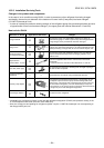
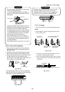
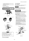
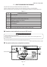
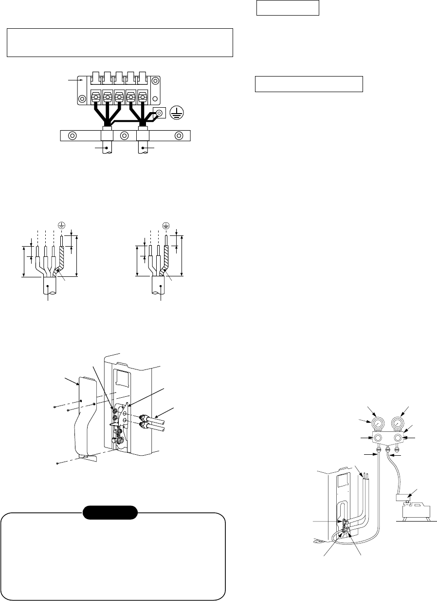
NOTE : Power supply cord
• Wire type : minimum AWG14
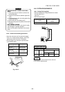
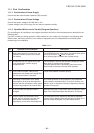
Stripping length of the Power supply cord
and Inter connecting cable
L
1
L
2
L
1
L
2
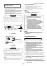
S
Inter connecting cable
Power supply cord
Terminal block
Unit : inch (mm)
L
1
L
2
L
1
L
2
S
Ground line
Connecting cable Power cord
Ground line
3/8 (10)
3/8 (10)
1-3/16 (30)
2-12/16 (70)
3/8 (10)
3/8 (10)
1-3/16 (30)
1-9/16 (40)
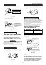
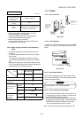
Conduit plate
Connector
Lock nut
Valve cover
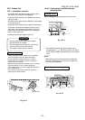
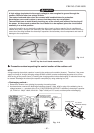
•
Wrong wiring connection may cause some
electrical parts burn out.
•
Be sure to comply with LOCAL CODES.
•
Every wire must be connected firmly.
•
If incorrect or incomplete wiring is carried out,
it will cause an ignition or smoke.
CAUTION
Fig. 10-4-4
Fig. 10-4-5
Fig. 10-4-6
NOTE : Inter connecting cable
• Wire type : minimum AWG14
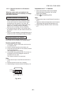
10-5. EVACUATING
10-5-1. Evacuating
After the piping has been connected to the indoor unit,
you can perform vacuuming together at once.
Vacuuming
Evacuate the air in the connecting pipes and in the
indoor unit using a vacuum pump. Do not use the
refrigerant in the outdoor unit. For details, see the
manual of the vacuum pump.
Using a vacuum pump
Be sure to use a vacuum pump with counter-flow
prevention function so that inside oil of the pump does
not flow backward into pipes of the air conditioner
when the pump stops.
(If oil inside of the vacuum pump enters the air
conditioner, which use R410A, refrigeration cycle
trouble may happen.)
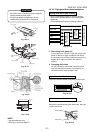
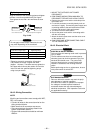
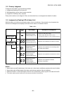
1. Connect the charge hose from the manifold valve
to the service port of the packed valve at gas side.
2. Connect the charge hose to the port of the vacuum
pump.
3. Open fully the low pressure side handle of the
gauge manifold valve.
4. Operate the vacuum pump to start evacuating.
Perform evacuating for about 15 minutes if the
piping length is 66 feet (20 m). (15 minutes for
66 feet) (assuming a pump capacity of 27 liters
per minute) Then confirm that the compound
pressure gauge reading is -101 kPa (-76 cmHg).
5. Close the low pressure side valve handle of the
gauge manifold valve.
6. Open fully the valve stem of the packed valves
(both gas and liquid sides).
7. Remove the charging hose from the service port.
8. Securely tighten the caps on the packed valves.
FILE NO. SVM-10020
– 62 –
Packed valve at
liquid side
Service port (Valve core
(Setting pin))
Packed valve at gas side
Vacuum
pump
Vacuum pump adapter for
counter-flow prevention
(For R410A only)
Charge hose
(For R410A only)
Handle Hi
(Keep full closed)
Manifold valve
Pressure gauge
Compound pressure gauge
Handle Lo
Charge hose
(For R410A only)
Connecting pipe
–101 kPa
(–76 cmHg)
Fig. 10-5-1