


– 55 –
10-3. Indoor Unit
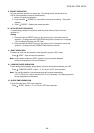
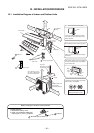
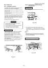
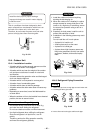
10-3-1. Installation Location
• A location which provides enough spaces around
the indoor unit as shown in the diagram.
• A location where there are no obstacle near the air
inlet and outlet.
• A location which allows easy installation of the piping
to the outdoor unit.
• A location which allows the front panel to be opened.
• The indoor unit shall be installed so that the top of
the indoor unit is positioned at least 6.6 ft (2 m) in
• Location that will bear weight of the unit.
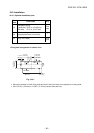
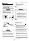
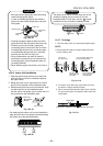
Remote controller
• Should be placed where there are no obstacles,
such as curtains, that may block the signal.
• Do not install the remote controller in a place
exposed to direct sunlight or close to a heating
source, such as a stove.
• Keep the remote controller at least 3.3 ft (1 m) away
from the nearest TV set or stereo equipment.
(This is necessary to prevent image disturbances or
noise interference.)
• The location of the remote controller should be
determined as shown below.
Fig. 10-3-1
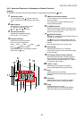
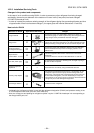
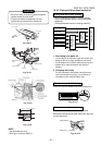
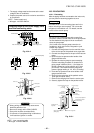
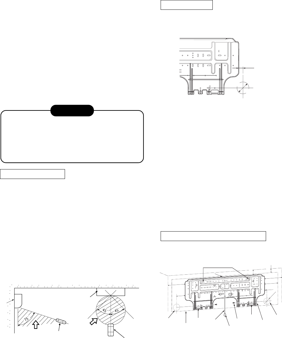
10-3-2. Cutting a Hole and Mounting the
mounting Plate
Cutting a hole
When installing the refrigerant pipes from the rear.
1. After determining the pipe hole position on the
mounting plate (
ð
), drill the pipe hole ∅ 2-9/16 in.
(∅ 65 mm) at a slight downward slant to the outdoor
side.
NOTE :
• When drilling into a wall that contains a metal lath,
wire lath or metal plate, be sure to use a pipe hole
brim ring sold separately.
Mounting the mounting plate
Indoor unit
(Top view)
(Side view)
Remote
controller
Remote controller
Indoor unit
Reception
range
Reception
range
Fig. 10-3-2
FILE NO. SVM-10020
height. Also, it must be avoided to put anything on
the top of the indoor unit.
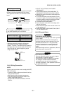
CAUTION
• Direct sunlight on the indoor unit wireless
receiver should be avoided.
• The microprocessor in the indoor unit should
not be too close to RF noise sources.
(For details, see the owner's manual.)
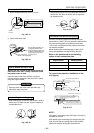
Fig. 10-3-3
m from the right side edge is
e center of pipe hole
35 120 180 240
The center of the pipe hole is above
the arrow.
Pipe hole
14/16 in.
(23 mm)
Ø2-9/16 in. (65 mm)
To
uni
t
ou
t line
24
0mm
To u
ni
t o
ut l
i
ne
35mm
T
o
un
it
out li
ne
2
40m
m
Offset 23mm from the right side edge is
the center of pipe hole
To unit out l
i
ne
120
m
m
0
23
35 12
018
02
4
0
Offset 85mm from the left side edge is
the center of pipe hole
1
7
Anchor bolt holes
Hook
Hook
Hook
Pipe hole
Pipe hole
Ø2-9/16 in.
(Ø65 mm)
Mounting plate
Weight
Indoor unit
Thread
6.6 ft (2 m) or more
from fl oor
Mounting
Screw
7 in.
(170 mm)
3-11/32 in.
(85 mm)
Ø2-9/16 in.
(65 mm)
1 in.
(23 mm)
5 in.
(132 mm)
7 in.
(170 mm)
2 in.
(50 mm)
1-1/2 in.
(40 mm)