


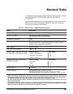

Specifications
TDS 520A, 524A, 540A, & 544A Performance Verification
General Purpose Knob
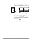
Assign the general purpose knob to adjust a selected parameter function.
More quickly change parameters by toggling the SHIFT button. Use the same
method as for
selecting
a function, except the final side-menu selection
assigns the general purpose knob to
adjust
some function, such as the posi-
tion of measurement cursors on screen, or the setting for a channels fine
gain.
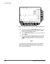
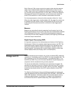
GUI
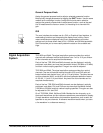
The user interface also makes use of a GUI, or Graphical User Interface, to
make setting functions and interpreting the display more intuitive. Some
menus and status are displayed using iconic representations of function
settings such as those shown here for full, 100 MHz, and 20 MHz bandwidth.
Such icons allow you to more readily determine status or the available set-
tings.
TDS 540A and 544A: The signal acquisition system provides four vertical
channels with calibrated vertical scale factors from 1 mV to 10 V per division.
All four channels can be acquired simultaneously.
Each of the four TDS 540A and 544A channels can be displayed, vertically
positioned, and offset, can have their bandwidth limited (100 MHz or 20 MHz)
and their vertical coupling specified. Fine gain can also be adjusted.
TDS 520A and 524A: The signal acquisition system provides four vertical
channels. Two are full-featured vertical channels (CH1 and CH2) with cali-
brated vertical scale factors from 1 mV to 10 V per division. The other two are
auxiliary channels (AUX1 and AUX2) with three calibrated deflection factors
of 100 mV, 1 V, and 10 V per division. Any two of the four channels can be
acquired simultaneously.
Each of the four TDS 520A and 524A channels can be displayed, vertically
positioned, and offset. CH1 and CH2 can also have their bandwidth limited
(100 MHz or 20 MHz) and their vertical coupling specified. Fine gain can also
be adjusted for CH1 and CH2.
On all TDS 520A, 524A, 540A and 544A: Besides the four channels, up to
three math waveforms and four reference waveforms are available for display.
(A math waveform results when dual waveform operations, such as add, are
specified on any two channels. A reference waveform results when you save
a live waveform in a reference memory.)
Signal Acquisition
System