


Performance Tests
Performance Verification Procedures
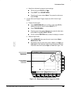
3. Check Jitter vs. Signal Amplitude
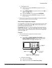
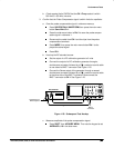
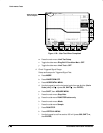
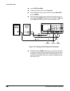
a. Setup equipment for Jitter Test (See Figure 1-27).
Connect one of the rear panel composite outputs marked
COMPST on the TSG121 through a 75 cable and a 75
terminator to the oscilloscope CH1 input.
Press the PAL signal source 100% FIELD control (the fourth
TSG121 front-panel button from the left).
75 Cable
PAL Signal
Source
TSG121
COMPST
75
Terminator
Figure 1-27: Jitter Test Hookup
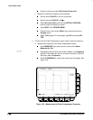
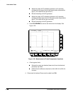
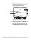
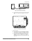
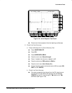
b. CHECK that the oscilloscope lights up its front panel TRIG’D LED
and it displays the waveform on screen (See Figure 1-28).
Figure 1-28: Jitter Test Displayed Waveform