Specifications
Specifications
Specialized display modes, such as variable persistence (with color
coding on the TDS 524A and 544A), dot or vector mode, sin(x)/x or linear
display filters, and, on the TDS 524A and 544A, user selectable color
palettes. The “Fit to Screen” feature compresses the entire waveform
record to fit on the screen.
A complement of advanced acquisition modes such as peak-detect,
high-resolution, sample, envelope, and average. The FastFrame
TM
feature acquires waveforms in rapid succession with a minimum of dead
time between acquisitions. FastFrame
TM
allows acquisition rates of up to
50,000 frames per second.
A unique graphical user interface (GUI), an on-board help mode, and a
logical front-panel layout which combine to deliver a new standard in
usability.
VGA output for driving remote monitors.
A 1.44 Mbyte, DOS 3.3 or later, floppy disk drive for saving waveforms,
color images, and oscilloscope setups (standard on the TDS 524A and
544A and optional, as option 1F, on the TDS 520A and 540A). Also, all
TDS 500A have built-in NVRAM storage for saving waveforms and set-
ups.
On the 524A and 544A, a color display for distinguishing among wave-
forms, their measurements, and associated text.
Use a combination of front-panel buttons, knobs, and on-screen menus to
control the many functions of these oscilloscopes. The front-panel controls
are grouped according to function: vertical, horizontal, trigger, and special.
Set a function you adjust often, such as vertical positioning or the time base
setting, directly by its own front-panel knob. Set functions which you change
less often, such as vertical coupling and horizontal mode, indirectly using
selected menus.
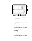
Menus
Pressing one (sometimes two) front-panel button(s), such as vertical menu,
displays a
main
menu of related functions, such as coupling, bandwidth, etc.,
at the bottom of the screen. Pressing a main-menu button, such as coupling,
displays a
side
menu of settings for that function, such as AC, DC, or GND
(ground) coupling, at the right side of the screen. Pressing a side-menu
button selects a setting such as DC.
Indicators
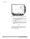
On-screen readouts help you keep track of the settings for various functions,
such as vertical and horizontal scale and trigger level. Some readouts use the
cursors or the automatic parameter extraction feature (called measure) to
display the results of measurements made or the status of the instrument.
User Interface


