


Performance Tests
TDS 520A, 524A, 540A, & 544A Performance Verification
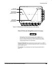
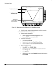
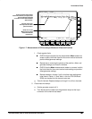
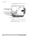
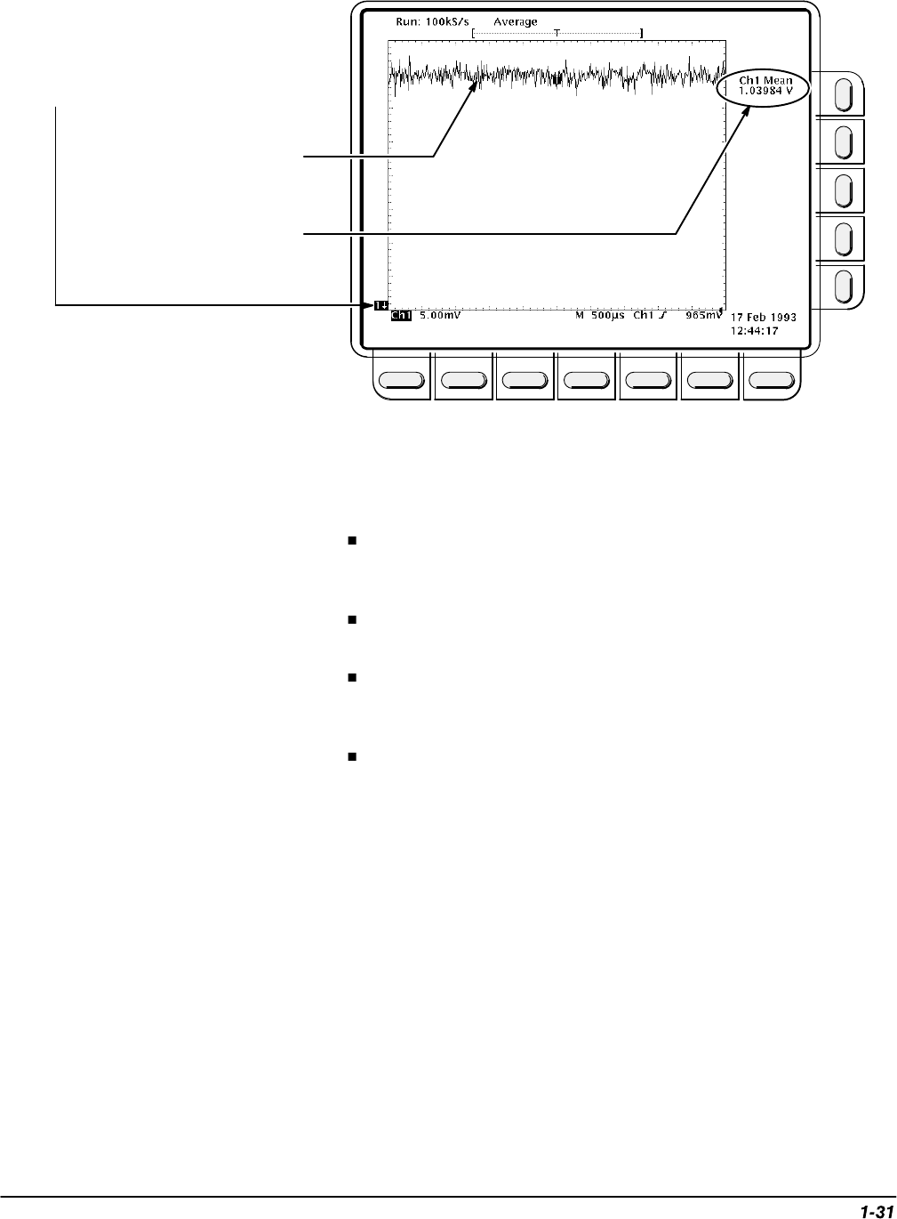
Third, turn on the
Measurement called
mean and read the
results here.
Second, input a DC
level equal to the offset
plus 3 divisions.
First set vertical and position
offsets to maximum (no input). Note
gnd ref indicator bounded
on-screen for the offset baseline
below screen.
Figure 1-7: Measurement of DC Accuracy at Maximum Offset and Position
f.
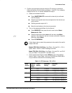
Check against limits:
CHECK that the readout for the measurement Mean readout on
screen is within the limits listed
for the current vertical scale and
position/offset/generator settings.
Repeat step d, reversing the polarity of the position, offset, and
generator settings as is listed in the table.
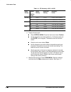
CHECK that the Mean measurement readout on screen is within
the limits listed
for the current vertical scale setting and position/
offset/generator settings.
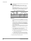
Repeat substeps c through f until all vertical scale settings set-
tings listed in Table 1-3 (and Table 1-4 for the TDS 520A and
524A) are checked for the channel under test.
g.
Test all channels:
Repeat substeps a through f for all four channels.
5.
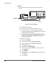
Disconnect the hookup:
a.
Set the generator output to 0 V
.
b. Then disconnect the cable from the generator output at the input
connector of the channel last tested.