


Performance Tests
TDS 520A, 524A, 540A, & 544A Performance Verification
4.
Confirm input channels are within limits for DC accuracy at maximum
offset and position:
Do the following substeps — test CH 1 first,
skipping
substep a since CH 1 is already selected from step 3.
a.
Select an unchecked channel:
Press WAVEFORM OFF to remove the channel just confirmed
from the display.
Press the front-panel button that corresponds to the channel you
are to confirm.
Set the generator output to 0 V.
Move the test hookup to the channel you select.
b.
Turn on the measurement Mean for the channel:
Press MEASURE, then press the main-menu button Select
Measrmnt for
CHx
.
Press the side menu button more until the menu label Mean
appears in the side menu (its icon is shown at the left). Press the
side-menu button Mean.
Press CLEAR MENU.
Follow these rules to match this procedure to the model of the oscillo-
scope under test:
Models TDS 540A, 544A Only—Use Table 1-3 to test CH 1—CH 4;
ignore Table 1-4 AUX 1 & AUX 2 settings and limits.
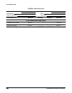
Model TDS 520A, 524A Only—Use Table 1-3 to test CH 1 and CH 2
only; use Table 1-4 to test AUX 1 and AUX 2 only.
c.
Set its vertical scale:
Set the vertical SCALE to one of the settings
listed in Table 1-3 (and Table 1-4 for the TDS 520A and 524A) that is
not yet checked. (Start with the first setting listed.)
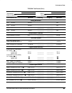
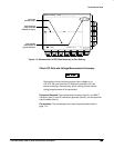
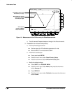
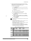
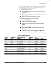
Table 1-3: DC Accuracy: CH 1–CH 4
Scale
Setting
Position
Setting
(Divs)
Offset
Setting
Generator
Setting
Accuracy
Limits
5mV –5 +1 V +1.040 V +1.0355 V to +1.0445 V
+5 –1 V –1.040 V –1.0355 V to –1.0445 V
200 mV –5 +10 V +11.6 V +11.525 V to +11.675 V
+5 –10 V –11.6 V –11.525 V to –11.675 V
1V –5 +100 V +108 V +107.450 V to +108.550 V
+5 –100 V –108 V –107.450 V to –108.550 V