Typical Characteristics
Specifications
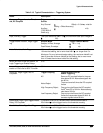
Table 2-15: Typical Characteristics — Triggering System (Cont.)
Name Description
Sensitivities, Pulse-Type Trigger Width
and Glitch
6
1.0 division with a minimum slew rate of 25 div/ s at the trigger level
or the threshold crossing. For <5 nsec pulse width or rearm time,
2 divisions are required.
Sensitivities, Derating Aux Channel Trig-
ger (TDS 520A & 524A)
All trigger sensitivity specifications are derated by 50% for AUX 1 and
AUX2 inputs.
Sync Width (Option 05 Video Trigger) min. 400 ns for HDTV signals
Sync Duty Cycle
(Option 05 Video Trigger)
min. 50 to 1
Hum Rejection
(Option 05 Video Trigger)
NTSC and PAL: –20 dB without any trigger spec deterioration. Trig-
gering will continue down to 0 dB with some performance deteriora-
tion.
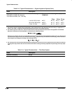
1 The trigger position errors are typically less than the values given here. These values are for triggering signals having a slew rate at
the trigger point of
division/ns.
2 The waveform interval (WI) is the time between the samples in the waveform record. Also, see the footnote for the characteristics
Sample Rate Range
and
Equivalent Time or Interpolated Waveform Rates
in Table 2-3 on page 2-10.
3 The minimum pulse width and rearm width required for logic-type triggering or events delaying to occur.
4 The minimum sensitivity for obtaining a stable trigger. A stable trigger results in a uniform, regular display triggered on the selected
slope. The trigger point must not switch between opposite slopes on the waveform, and the display must not “roll” across the
screen on successive acquisitions. The TRIG’D LED stays constantly lighted when the SEC/DIV setting is 2 ms or faster but may
flash when the SEC/DIV setting is 10 ms or slower.
5 See the characteristic
Sensitivity, Edge-Type Trigger, DC Coupled
in Table 2-10, which begins on page 2-17.
6 The minimum signal levels required for stable logic or pulse triggering of an acquisition or for stable counting of a DC-coupled
events delay signal. Also, see the footnote for
Sensitivity, Edge-Type Trigger, DC Coupled
in this table. (Stable counting of events is
counting that misses no events.)
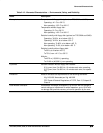
Table 2-16: Typical Characteristics — Data Handling
Name
Description
Time, Data-Retention, Nonvolatile
Memory
1,2
Battery life is 5 years
Floppy disk
Standard on TDS 540A, 544A
Option 1F on TDS 520A, 524A
3.5 inch, 720 K or 1.44 Mbyte, DOS 3.3-or-later compatible
1 The time that reference waveforms, stored setups, and calibration constants are retained when there is no power to the oscillo-
scope.
2 Data is maintained by small lithium-thionyl-chloride batteries internal to the memory ICs. The amount of lithium is so small in these
ICs that they can typically be safely disposed of with ordinary garbage in a sanitary landfill.


