


Performance Tests
Performance Verification Procedures
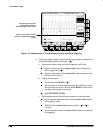
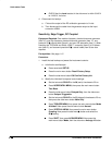
CHECK that the Level readout in the side menu is within 9.940 V
to 10.060 V, inclusive.
4.
Disconnect the hookup:
a.
First set the output of the DC calibration generator to 0 volts.
b. Then disconnect the cable from the generator output at the input
connector of CH 1.
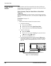
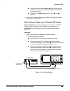
Sensitivity, Edge Trigger, DC Coupled
Equipment Required:
One medium-frequency leveled sine wave generator
(Item 10), one high-frequency leveled sine wave generator (Item 11), one
precision 50 coaxial cable (Item 4), and one 10X attenuator (Item 1). When
checking the TDS 540A and 544A, a BNC T connector (Item 6), a 5X attenu-
ator (Item 2), and a second precision 50 coaxial cable (Item 4) are also
required.
Prerequisites:
See page 1-15.
Procedure:
1.
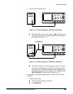
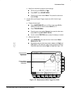
Install the test hookup and preset the instrument controls:
a.
Initialize the oscilloscope:
Press save/recall SETUP.
Press the main-menu button Recall Factory Setup.
Press the side-menu button OK Confirm Factory Init.
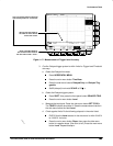
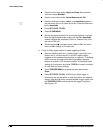
b.
Modify the initialized front-panel control settings:
Set the horizontal SCALE for the M (main) time base to 20 ns.
Press HORIZONTAL MENU; then press the main-menu button
Time Base.
Press the side-menu button Delayed Only; then the side-menu
button Delayed Triggerable.
Set the horizontal SCALE for the D (delayed) time base to 20 ns;
then press the side-menu button Main Only.
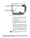
Press TRIGGER MENU; then press the main-menu button Mode
& Holdoff. Now press the side-menu button Normal.
Press VERTICAL MENU; then press the main-menu button
Coupling. Now press the side-menu button and select the
50 setting.
Press SHIFT; then press ACQUIRE MENU. Now press the
main-menu button Mode; then the side-menu Average 16 button.