


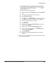

Performance Tests
TDS 520A, 524A, 540A, & 544A Performance Verification
c.
Hook up the test-signal source:
Medium
Frequency
Sine Wave
Generator
Output
50 Coaxial Cables
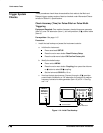
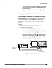
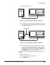
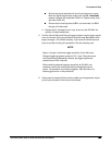
Figure 1-18: Initial Test Hookup—TDS 520A or 524A Only
TDS 520A, 524A only: Connect, through a 50 precision coaxial
cable, the signal output of a medium-frequency sine wave gener-
ator to CH 1. See Figure 1-18.
Medium
Frequency
Sine Wave
Generator
To AUX TRIG INPUT
on Rear Panel
Output
50 Coaxial Cables
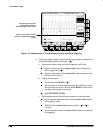
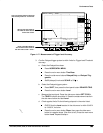
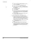
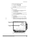
Figure 1-19: Initial Test Hookup—TDS 540A or 544A Only
TDS 540A or 544A only: Connect the signal output of a medium-
frequency sine wave generator to a BNC T connector. Connect
one output of the T connector to CH 1 through a 50 precision
coaxial cable; connect the other output of the T connector to the
AUX TRIG INPUT at the rear panel. See Figure 1-19.
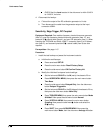
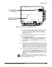
2.
Confirm Main and Delayed trigger systems are within sensitivity limits
(50 MHz):
a.
Display the test signal:
Set the generator frequency to 50 MHz.
Press MEASURE.