


Performance Tests
TDS 520A, 524A, 540A, & 544A Performance Verification
b.
Check against limits:
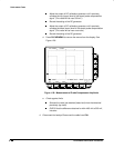
CHECK that the CH 1 Freq readout is within
950 Hz to 1.050 kHz, inclusive.
3.
Confirm that the Probe Compensator signal is within limits for amplitude:
a.
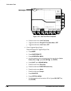
Save the probe compensation signal in reference memory:
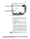
Press SAVE/RECALL WAVEFORM; then press the main-menu
button Save Wfm
Ch 1
.
Press the side-menu button to Ref 1 to save the probe compen-
sation signal in reference 1.
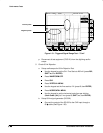
Disconnect the cable from CH 1 and the clips from the probe
compensation terminals.
Press MORE; then press the main-menu button Ref 1 to dis-
played the stored signal.
Press CH 1.
b.
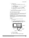
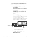
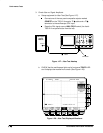
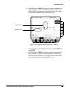
Hook up the DC standard source:
Set the output of a DC calibration generator to 0 volts.
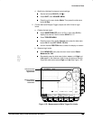
Connect the output of a DC calibration generator through a
dual-banana connector followed by a 50 precision coaxial cable
to one side of a BNC T connector. See Figure 1-25.
Connect the Sense output of the generator through a second
dual-banana connector followed by a 50 precision coaxial cable
to the other side of the BNC T connector. Now connect the
BNC T connector to CH 1. See Figure 1-25.
HI
LO
Output Sense
DC Calibrator
50
Coaxial Cables
Dual Banana to
BNC Adapters
BNC T
Connector
Figure 1-25: Subsequent Test Hookup
c.
Measure amplitude of the probe compensation signal:
Press SHIFT; then ACQUIRE MENU. Then use the keypad to set
AVERAGE to 16 in the side menu.