Brief Procedures
Performance Verification Procedures
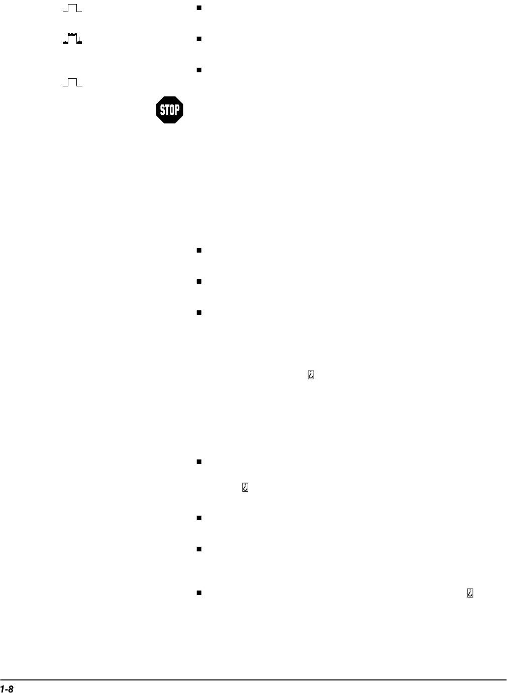
Hi Res mode displays an actively acquiring waveform on-screen
with the noise that was present in Sample mode reduced.
Envelope mode displays an actively acquiring waveform on-
screen with the noise displayed.
Average mode displays an actively acquiring waveform on-
screen with the noise reduced like in Hi Res mode.
TDS 520A and 524A only: Substep e will have you repeat the pre-
vious substeps to check all input channels. Be sure to check only CH
1 and CH 2 when testing the TDS 520A or 524A. (Step 3 will test the
AUX 1 and AUX 2 inputs.) When testing the TDS 540A or 544A, test
all four channels, CH 1 through CH 4.)
e.
Test all channels:
Repeat substeps a through d until all four input
channels are verified.
3.
TDS 520A and 524A Only: Verify auxiliary inputs operate:
Perform the
following substeps when checking the AUX 1 and AUX 2 inputs only.
a.
Select an auxiliary channel:
Press WAVEFORM OFF to remove from display the channel just
verified.
Press the front-panel button that corresponds to the channel you
are to verify.
Move probe to the channel you selected.
b.
Set up the selected channel:
Press AUTOSET to obtain a viewable
display in the selected channel.
The display obtained might not trigger stably because autoset cannot
provide more than about
signal
amplitude in an auxiliary channel equipped with a 10X probe. This
amount is less than the minimum trigger sensitivity for auxiliary
channel trigger sources; therefore, triggering is not required.
c.
Verify that the channel is operational:
Confirm that the following
statements are true.
The vertical scale readout for the channel under test shows a
setting of 1 V, and a square-wave probe-compensation signal
about
on
page 1-3 to locate the readout.)
The vertical POSITION knob moves the signal up and down the
screen when rotated.
Turning the vertical SCALE knob counterclockwise to 10 V
decreases the amplitude of the waveform on-screen. (The ampli-
tude will drop to near zero when doing this substep.)
Returning the knob to 1 V returns the amplitude to about
divi-
sion.
d.
Verify that the channel acquires in all acquisition modes:
Disconnect
the probe ground lead from the probe-compensation terminal. Do
step 2, substep d to verify the five acquire modes.
