


Performance Tests
Performance Verification Procedures
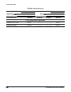
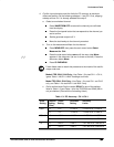
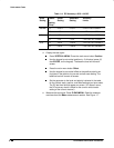
Table 1-4: DC Accuracy: AUX 1–AUX 2
Scale
Setting
Positio
n
Setting
(Divs)
Offset
Setting
Generator
Setting
Accuracy
Limits
100 mV –5 +0.5 V +1.3 V +1.271 V to +1.329 V
+5 –0.5 V –1.3 V –1.271 V to –1.329 V
1 V –5 +5 V +13 V +12.710 V to +13.290 V
+5 –5 V –13 V –12.710 V to –13.290 V
10 V –5 +50 V +130 V +127.10 V to +132.90 V
+5 –50 V –130 V –127.10 V to –132.90 V
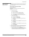
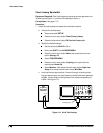
d.
Display the test signal:
Press VERTICAL MENU. Press the main-menu button Position.
Use the keypad to set vertical position to –5 divisions (press –5,
then ENTER, on the keypad). The baseline level will move off
screen.
Press the main-menu button Offset.
Use the keypad to set vertical offset to the positive-polarity set-
ting listed in the table for the current vertical scale setting. The
baseline level will remain off screen.
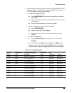
Set the generator to the level and polarity indicated in the table
for the vertical scale, position, and offset settings you have made.
The DC test level should appear on screen. (If it doesn’t return,
the DC accuracy check is failed for the current vertical scale
setting of the current channel.)
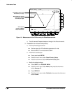
e.
Measure the test signal:
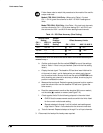
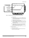
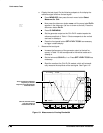
Press CLEAR MENU. Read the measure-
ment results at the Mean measurement readout. See Figure 1-7.