


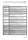
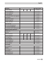

12.4 Technical data
Inputs
7 configurable inputs for sensors (Pt 100 and PTC or
Pt 100 and Pt 1000 or Pt 100 and NTC) or binary alarms
1 outdoor temperature input for sensor or current signal 4 (0) to 20 mA
1 flow temperature sensor input
Sensor inputs
Binary inputs BE1 optionally for releasing a control circuit or external demand
BE5 configurable for storage tank thermostat
Other inputs Pulse or current input for capacity or flow rate limitation
Remote control to correct the room temperature and select the operating mode
Alternatively, potentiometer input 1 to 2 kΩor configurable for binary alarm
Outputs
Three-step signals: Load 250 V AC, max. 2 A, min. 10 mA
On-off signals: Load 250 V AC, max. 2 A, min. 10 mA
Varistor suppression 300 V
Control signal outputs
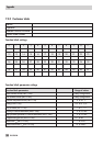
Binary outputs Max. 4 outputs to control pumps,
load 250 V AC, max. 2 A, min. 10 mA, varistor suppression 300 V
2 reed relay outputs for controlling the speed of a circulation pump or for
fault indication, load max. 24 V, 100 mA
Interfaces Serial RS-485 interface for connection to four-wire bus, protocol: Modbus
RTU, data format 8N1or serial RS-232-C interface for connection to a
modem; connection over RJ-12 jack
Option: Meter bus interface
Operating voltage 230 V AC (+ 10 %/–15 %), 48 to 62 Hz
Power supply failure: All parameter settings and configuration data are
stored in an EEPROM in the case of power failure
Power consumption Approx. 3 VA
Temperature range Operation: 0 to 40 °C (avoid long periods of heat) Storage: –20 to 60 °C
Degree and class of
protection
IP 40 according to IEC 529 and II according to VDE 0106
Degree of contamination 2 according to VDE 0110
Overvoltage category II according to VDE 0110
Humidity rating F according to VDE 40040
Noise immunity According to EN 61000-6-1
Noise emission According to EN 61000-6-3
Weight Approx. 0.6 kg
EB 5476 EN 99
Appendix