


Connecting the sensors
Cables with a minimum cross-section of 2 x 0.5 mm² can be connected to the terminals at the
back panel of the housing.
Connecting the actuators
Connect cables with at least 1.5 mm² suitable for damp locations to the terminals of the control
-
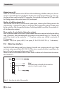
ler output. The direction of travel needs to be checked at start-up.
4
Set slide switch to (+). Valves must open.
4
Set slide switch to (–). Valves must close.
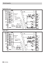
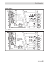
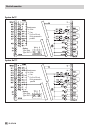
Connecting the pumps
Connect all cables with atleast 1.5 mm² to the terminals ofthe controller as illustrated in the corre
-
sponding wiring diagram (–> page 78 to 80).
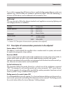
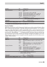
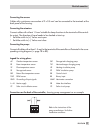
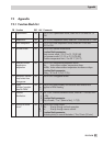
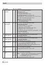
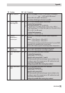
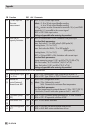
Legend for wiring plans:
AF Outdoor temperature sensor SLP Storage tank charging pump
RF Room temperature sensor TLP Heat exchanger charging pump
VF Flow temperature sensor UP Heating circulation pump
SF Storage tank sensor ZP DHW circulation pump
RüF Return flow temperature sensor RK Control circuit
TWF DHW sensor BE Binary input
GND Grounding of input signals WMZ Heat meter connection
L + N Mains supply ZB Meter bus interface
CF Solar circuit collector sensor CP Solar circuit pump
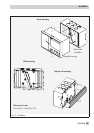
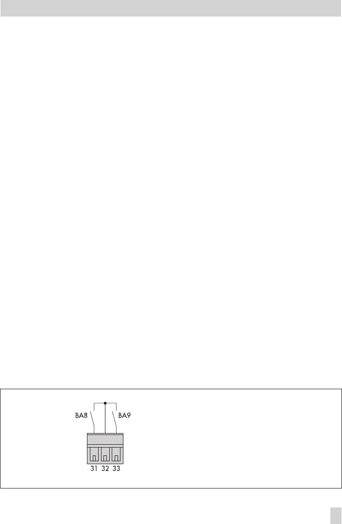
Connections on the back of the controller, showing pump management as an example
EB 5476 EN 77
Electrical connection
Refer to the instructions of the
pump manufacturer for further
installation conditions.