


8 Operational faults
Malfunctions or faults are indicated by the icon blinking on the display.
8.1 Sensor failure
The following list explains how the controller responds to the failure of the different sensors.
Safety functions such as frost protection and excess temperature protection no longer work
when a sensor fails.
4
Outdoor sensor AF: When the outdoor sensor fails, the controller uses a flow temperature
set point of 50 °C or the
Max. flow temperature
(when the
Max. flow temperature
is smaller
than 50 °C).
4
Flow sensor in heating circuit VF1/VF2: When the flow sensor is defective, the controller
continues to work with the associated valve in the 30 % valve position. DHW heating which
uses such asensor to measure the chargingtemperature is interrupted. Insystems Anl 4, 5, 6
and 11, the failure of flow sensor VF2 cause the DHW control valve to close.
4
Flow sensor in DHW circuit VF3: When the flow sensor VF3 is defective, the DHW heating
takes place without change in lag/lead sequence.
4
Return flow sensor RüF1/RüF2: The controller continues to function without the return tem-
perature limitation when the return flow sensor fails.
4
Room sensor RF: The controller functions using the settings for operation without room sen-
sor when the room sensorfails. For example, optimization mode switchesto the reduced op-
eration mode. Adaptation mode is interrupted. The last defined heating characteristic is not
changed anymore.
4
Storage tank sensor SF1/SF 2: When one of the sensors fail, DHW heating no longer takes
place.
4
Solar circuit sensor SF2/CF: When one of the sensors fails, the solar circuit pump is
switched off.
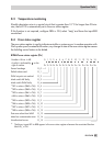
8.2 Collective error alarm
As an alternative tothe Pump management function, a fault alarmcan be indicated over the bi
-
nary output BA8. Should the error status register FSr indicate a fault, the binary output BA8 is
activated.
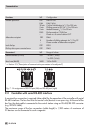
Function
WE Configuration
Fault alarm output BA8 OFF FB47 = ON
64 EB 5476 EN
Operational faults