


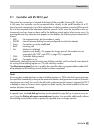

Note!
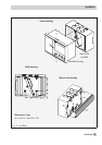
A 15 V DC supply voltage (+15V at terminal 15 connectedto the meter bus connection terminal
3) can be used at the WMZ connection of TROVIS 5476 Controller when the red jumper on the
back of the controller is located pointing towards the edge of the controller (Fig. 8). Otherwise,
the meter bus module in the heat meter is supplied. Furthermore, the heat meter is galvanically
connected with controller input side (pulse and current input at terminal 15) resulting it being
connected to the Modbus interface as well which can lead to the communication coming to a
standstill.
9.4.1 Activating the meter bus
To successfully transfer data from the heat meter to the controller, the heat meter must use a
standardized protocol inaccordance with EN 1434-3.It is not possible tomake a general state
-
ment about whichspecific data can be accessedin each meter. For detailson the different meter
makes, refer to the technical documentation TV-SK 6311. All necessary function block parame-
ters to set upthe communication with heator water meters are availablein function block FB 29.
The meter bus address, the model code and the reading mode must be specified for the heat
meters WMZ1 to WMZ3.
A meter bus address must be unique and correspond with the address preset in the WMZ. If the
preset meter bus address is unknown, a single heat meter connected to the controller can be as-
signed the meter bus address 254. The address 255 deactivates the communication with the re-
spective WMZ. Themodel code to be setfor the heat meter canbe found in TV-SK 6311.In gen-
eral, the default setting of 1434 canbe used for most devices. The meters can be readeither au-
tomatically every 24 hours (approx.),continuously or when the coils (= Modbusdata points) as-
signed to the heat meters WMZ1 to WMZ3 are overwritten with the value 1 via the system bus
interface.
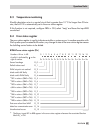
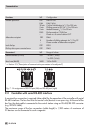
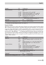
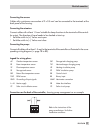
Function
WE Configuration
Meter bus OFF
254*
1434
Cont
FB29 = ON
Meter bus address for WMZ 1 to 3 (ST.-NO) / 0 to 255
Model code WMZ 1 to 3 / 1434, CAL3, APAtO, SLS
Reading mode WMZ 1 to 3 / 24h, Cont, CoiL
* WE for WMZ 2 and 3: 255
9.4.2 Flow rate and/or capacity limitation via meter bus
Similar to theflow rate limitation based ona standardized 0/4 to20 mA signal, theupdate rate
of the measured variable, flow rate and/or capacity, must be smaller than 5 seconds in meter
bus operation tocarry out a properlimitation. Refer to thetechnical documentation TV-SK 6311
EB 5476 EN 71
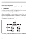
Communication