


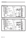
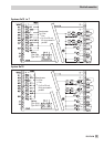
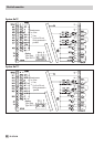
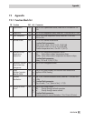

Parameter*
WE Range of values
* Parameter only needs setting with FB31 = ON, select “At“
9.5 Memory module
The use of a memory module (accessory no. 1400-7142) is particularly useful to transfer all
data from one TROVIS 5476 Controller to several other TROVIS 5476 Controllers. The memory
module is plugged into the RJ-12 jack integrated into the front panel. Once the module has
been connected, “76 SP“ is displayed. If the memory module already contains data from a dif
-
ferent TROVIS 5476 Controller, press the enter key until “SP 76" is displayed.
4
Pressing the enter key to confirm “76 SP“ causes the controller settings to be transferred to
the memory module.
4
Pressing the enter key to confirm “SP 76“ causes the saved controller settings to be trans
-
ferred from the memory module to the controller.
During the data transfer, the bars on the display indicate the progress. After the display stops,
remove the memory module from the controller.
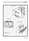
10 Installation
The controller consists of the housing with the electronics and the back panel with the terminals.
It is suitable for panel, wall, and top hat rail mounting (Fig. 9). To connect the wiring, undo the
fastening screw (1) at the front and separate the controller housing from the back of the control-
ler.
Panel mounting
1. Make a cut-out of 138 x 91 mm (width x height) in the control panel.
2. Insert the controller housing through the panel cut-out and turn the two plastic clamps (2)
on the front panel by 90°.
3. Install the electrical connections at the back of the housing as described in section 11.
4. Fit the controller housing back on.
Wall mounting
1. If necessary, bore holes with the specified dimensions in the appropriate places.
2. Fasten the back panel with four screws.
Perform steps 3. and 4. as describe for panel mounting
Top hat rail mounting
1. Fasten the spring-loaded hook (4) at the bottom of the top hat rail (3).
2. Slightly push the controller upwards and pull the upper hooks (5) over the top hat rail.
Perform steps 3. and 4. as describe for panel mounting
74 EB 5476 EN
Installation