


Quadra-Fire • QFP44 • 4051-300 Rev M • 09/0850
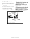
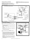
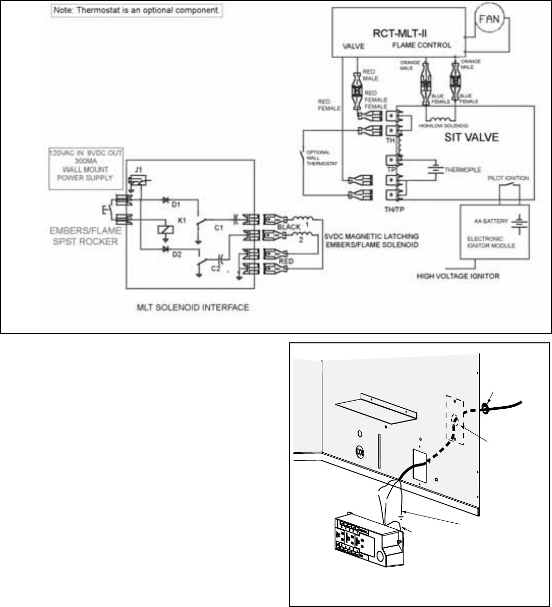
D. Electrical Service and Repair
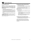
WARNING! Risk of Shock! Label all wires prior to
disconnection when servicing controls. Wiring errors can
cause improper and dangerous operation. Verify proper
operation after servicing.
Figure 12.1 Wiring Diagram
WARNING! Risk of Shock! Replace damaged wire with
type 105° C rated wire. Wire must have high temperature
insulation.
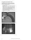
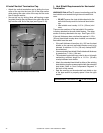
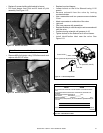
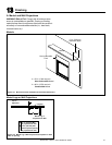
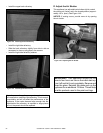
E. Junction Box Installation
If the box is being wired from the OUTSIDE of the appli-
ance:
• Remove the cover plate located on the outer shell - right
side (see Figure 12.2).
• Install the supplied Romex™ connector in the cover
plate.
• Feed the necessary length of wire through the
connector.
• Make all necessary wire connections and reattach the
cover plate to the outer shell.
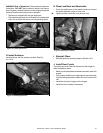
WHT
WHT
BLK
BLK
GRN wire
inside box
Copper
ground attached
to GRN screw with
GRN wire
14/2WG
Cover Plate
outside firebox
Romex
Connector
Figure 12.2 Junction Box Detail
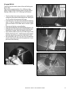
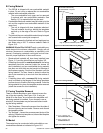
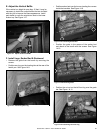
If the box is being wired from the INSIDE of the appli-
ance:
• Remove the screw attaching the junction box/receptacle
to the outer shell, rotate the junction box inward to
disengage it from the outer shell (see Figure 10.3).
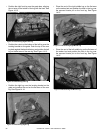
• Pull the electrical wires from outside the appliance
through this opening into the valve compartment.
• Feed the necessary length of wire through the
connector.
• Make all necessary wire connections to the junction box/
receptacle and reassemble the junction box/receptacle
to the outer shell.