


Quadra-Fire • QFP44 • 4051-300 Rev M • 09/0828
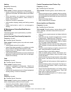
Dimension Descriptions
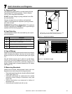
A Clearance above the ground, a veranda, porch, deck or balcony - 12 in.
(30 cm) minimum. *
B Clearance to window or door that may be opened – 10,000 BTUs or less,
6 in. (15 cm) minimum; 10,000-50,000 BTUs, 9 in. (23 cm) minimum; over
50,000 BTUs, 12 in. (30 cm) minimum. *
C Clearance to permanently closed window – 12 in. (30 cm) minimum -
recommended to prevent condensation on window.
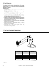
D Vertical clearance to ventilated sof t located above the termination within
a horizontal distance of 2 ft (60 cm) from the centerline of the termination
– 18 in. (46 cm) minimum. **
E Vertical clearance to unventilated sof t - 12 in. (30 cm) minimum. **
F Clearance to outside corner - 6 in. (15 cm) minimum.
G Clearance to inside corner - 6 in. (15 cm) minimum.
H Not to be installed above a meter/regulator assembly within 3 ft (90 cm)
horizontally* from the center line of the regulator (Canada only)
I Clearance to service regulator vent outlet – 3 ft (.91 m) U.S. minimum and
3 ft (.91 m) Canada minimum. *
J Clearance to non-mechanical air supply inlet into building or the combustion
air inlet to any other appliance – 9” (23 cm) U.S. minimum and 12 in. (30
cm) Canada minimum. *
K Clearance to mechanical air supply inlet - 3 ft (.91 m) U.S. minimum and
6 ft (1.8 m) Canada minimum. *
L Clearance above a paved sidewalk or paved driveway located on public
property - 7 ft (2.1 m) minimum.
A vent may not terminate directly above a sidewalk or paved driveway
which is located between two single family dwellings and serves both
dwellings.
M Clearance under veranda, porch, deck or balcony - 12 in. (30 cm) minimum.
* Recommended 30 in. (76 cm) for vinyl or plastic.
Only permitted if veranda, porch, deck or balcony is fully open on a
minimum of 2 sides beneath the oor. *
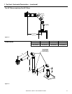
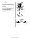
N Vertical clearance between two horizontal termination caps – 12 in. (30
cm) minimum.
O Horizontal clearance between two horizontal termination caps – 12 in. (30
cm) minimum.
P 6” - Non-vinyl sidewalls
12” – Vinyl sidewalls
Q 18” – Non-vinyl sof t and overhang
42” – Vinyl sof t and overhang
R 8 ft.
D
E
B
L
C
V
V
B
F
V
B
V
V
B
X
A
J
Fixed
Closed
M
V
K
X
RESTRICTION ZONE
(TERMINATION NOT
ALLOWED)
AIR SUPPLY INLET
X
GAS METER
V
TERMINATION CAP
H
B
Openable
Fixed
Closed
V
I
V
O
N
Q
P
R
T
S
E
lectrical
Service
V
U
V
U
V
W
D*
V
V
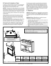
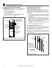
Covered Alcove
Applications
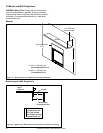
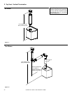
Clearances to Electrical Service
A
V
V
G
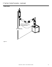
Measure horizontal clearances
from this surface.
Measure vertical clearances
from this surface
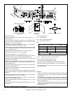
S
min
T
max
1 cap 3 ft 2 x S actual
2 caps 6 ft 1 x S actual
3 caps 9 ft 2/3 x S actual
4 caps 12 ft 1/2 x S actual
S
min
= # term caps x 3 T
max
= (2/# term caps) x S (actual)
U 6” min. – Clearance from sides of electrical service.
W 12” min. – Clearance above electrical service.
* As speci ed in CGA B149 Installation Codes
Note: Local codes or regulations may require different clearances.
** Clearance required to vinyl sof t material – 30 in. (76 cm) minimum.
Note: Location of the vent termination must not interfere with access to
the electrical service.
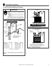
Figure 6.4 Minimum Clearances for Termination
CAUTION: IF EXTERIOR WALLS ARE FINISHED WITH VINYL SIDING, IT IS SUGGESTED THAT A VINYL PROTECTOR KIT BE INSTALLED.
WARNING!
In the U.S.: Vent system termination is NOT permitted in screened porches.
You must follow side wall, overhang and ground clearances as stated in
the instructions.
In Canada: Vent system termination is NOT permitted in screened porches.
Vent system termination is permitted in porch areas with two or more sides
open. You must follow all side wall, overhang and ground clearances as
stated in the instructions.
Hearth & Home Technologies assumes no responsibility for the improper
performance of the appliance when the venting system does not meet
these requirements.