


Quadra-Fire • QFP44 • 4051-300 Rev M • 09/08 23
B. Design and Installation Considerations
Quadra-Fire direct vent gas appliances are designed to
operate with all combustion air siphoned from outside of
the building and all exhaust gases expelled to the out-
side. No additional outside air source is required.
Installation MUST comply with local, regional, state and
national codes and regulations. Consult insurance carrier,
local building inspector, re of cials or authorities having
jurisdiction over restrictions, installation inspection and
permits.
Before installing, determine the following:
• Where the appliance is to be installed.
• The vent system con guration to be used.
• Gas supply piping.
• Electrical wiring requirements.
• Framing and nishing details.
• Whether optional accessories—devices such as a fan,
wall switch, or remote control—are desired.
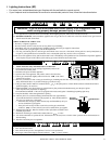
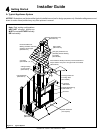
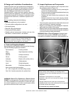
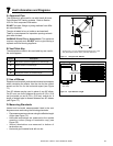
D. Inspect Appliance and Components
• Carefully remove the appliance and components from
the packaging (refer to Figure 4.2).
- Remove refractory from back of unit by removing the
screws from shipping bracket.
- Remove screws from shipping brackets before trying
to remove unit from pallet.
- Remove and save screws from andirons for later
installation.
- Remove screw from top of each carrying handle.
Handles have been provided to assist in moving the
unit.
• The vent system components and decorative doors and
fronts are shipped in separate packages.
• Report to your dealer any parts damaged in shipment,
particularly the condition of the glass.
• Read all of the instructions before starting the installation.
Follow these instructions carefully during the installation
to ensure maximum safety and bene t.
WARNING! Risk of Fire or Explosion! Damaged parts
could impair safe operation. DO NOT install damaged,
incomplete or substitute components. Keep appliance dry.
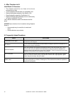
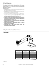
C. Tools and Supplies Needed
Before beginning the installation be sure that the following
tools and building supplies are available.
Tape measure Framing material
Pliers High temperature caulking
material
Hammer Phillips screwdriver
Gloves Framing square
Voltmeter Electric drill and bits (1/4 in.)
Plumb line Safety glasses
Level Reciprocating saw
Manometer Flat blade screwdriver
Non-corrosive leak check solution
1/2 - 3/4 in. length, #6 or #8 Self-drilling screws
One 1/4 in. female connection (for optional fan).
Hearth & Home Technologies disclaims any responsibility for,
and the warranty will be voided by, the following actions:
• Installation and use of any damaged appliance or vent system
component.
• Modi cation of the appliance or vent system.
• Installation other than as instructed by Hearth & Home
Technologies.
• Improper positioning of the gas logs or the glass door.
• Installation and/or use of any component part not approved
by Hearth & Home Technologies.
Any such action may cause a ¿ re hazard.
WARNING! Risk of Fire, Explosion or Electric Shock!
DO NOT use this appliance if any part has been under wa-
ter. Call a quali¿ ed service technician to inspect the appli-
ance and to replace any part of the control system and/or
gas control which has been under water.
Improper installation, adjustment, alteration, service or
maintenance can cause injury or property damage. For
assistance or additional information, consult a quali ed
service technician, service agency or your dealer.
Refractory
Shipping Brackets
Andirons
Figure 4.2 Refractory Shipping Location, Brackets