


2.0 General Layout
8
© Baxi Heating UK Ltd 2009
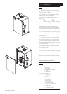
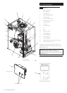
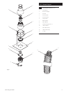
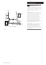
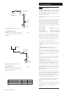
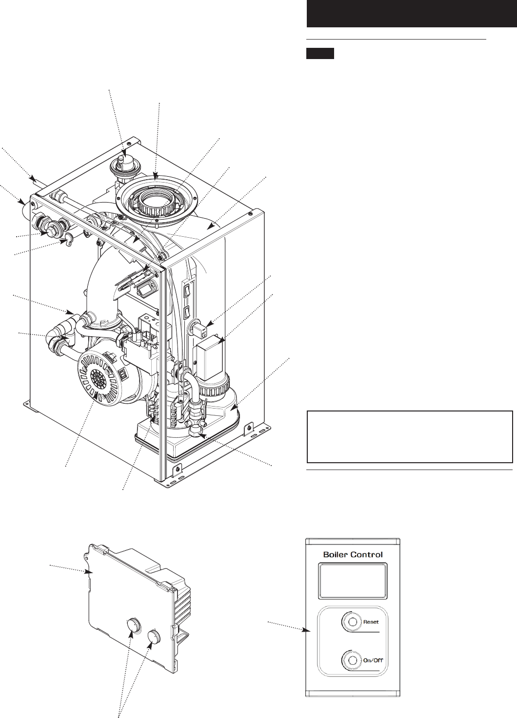
2.1 Layout (Fig. 3)
1. Automatic Air Vent
2. Flue Connection
3. Spark Generator
4. Spark & Sensing Electrodes
5. Heat Exchanger
6. Boiler Control Connector
7. Control Wiring Connector
8. Condensate Sump
9. Gas Cock
10. Condensate Pump
11. Fan
12. Drain
13. Return Connection
14. Air Sampling Point
15. Flue Sampling Point
16. Flow Connection
17. Condensate Outlet
18. PCB Control Box (shown removed for clarity)
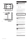
19. Boiler Control (cover open)
The Boiler Control operates the boiler remotely. This is
supplied with the firefront and is fitted, in operation, to the
firefront spacer frame.
IMPORTANT: To commission the boiler it is is necessary
to remove the Boiler Control from the firefront
packaging and connect it to the boiler at the upper right
hand side (item 6).
1
2
3
4
5
6
7
8
9
10
11
12
13
17
16
15
14
18
Calibration Controls
Fig. 3
19
PCB Control Box
removed for clarity
PCB Control Box