


4.0 System Details
14
© Baxi Heating UK Ltd 2009
4.7 Sealed Systems (cont)
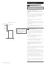
4. Expansion Vessel. A diaphragm type expansion vessel to
BS 4814:1 shall be fitted close to the inlet side of the pump.
The connecting pipework should not be less than 15mm.
Pipework connecting the expansion vessel should not
incorporate valves of any sort.
Methods of supporting the vessel are supplied by the vessel
manufacturer.
The nitrogen or air charge pressure of the expansion vessel
shall not be less than the hydrostatic head, (height of the
top point of the system above the expansion vessel). To
size the expansion vessel it is first necessary to calculate the
volume of water in the system in litres. The following
volumes may be used as a conservative guide to calculating
the system volume.
Boiler Heat Exchanger: 1.55 litres
Small Bore Pipework: 1 litre per kW of system output
Micro Bore Pipework: 7 litre
Steel Panel Radiators: 8 litre per kW of system output
Low Water Capacity Radiators: 1 litre per kW of system output
Hot Water Cylinder: 1 litre per kW of system output
If the system is extended, the expansion vessel volume may
have to be increased unless provision has been made for
extension. Where a vessel of the calculated size is not
available, the next available larger size should be used.
The boiler flow temperature is controlled at approx. 75°C.
The vessel size can now be determined from the
information in table 1 where V = System volume in litres.
5. Cylinder. The hot water cylinder must be an indirect
coiler type.
6. Method of Make Up. Provision shall be made for
replacing water loss from the system either:-
a) From a make up vessel or tank mounted in a position
higher than the top point of the system and connected
through a non-return valve to the system on the return side
of the hot water cylinder or the return side of all heat
emitters.
or
b) Where access to a make up vessel would be difficult by
using the mains top up method or a remote automatic
pressurisation and make up unit.
7. Mains Connection. There shall be no connection to the
mains water supply or to the water storage tank which
supplies domestic hot water even through a non-return
valve, without the approval of the Local Water Authority.
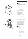
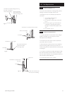
8. Filling Point. A filling point connection on the central
heating return pipework must be provided to facilitate initial
filling and pressurising and also any subsequent water loss
replacement/refilling.
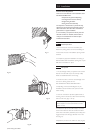
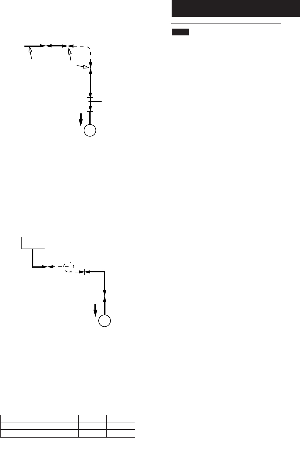
The sealed primary circuits may be filled or replenished by
means of a temporary connection between the circuit and a
supply pipe, provided a ‘Listed’ double check valve or some
other no less effective backflow prevention device is
permanently connected at the inlet to the circuit and the
temporary connection is removed after use.
The filling method adopted must be in accordance with all
relevant water supply regulations and use approved
equipment.
Your attention is drawn to: for GB: Guidance G24.2 and
recommendation R24.2 of the Water Regulations Guide. for
IE: the current edition of IS 813 “Domestic Gas
Installations”.
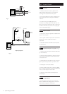
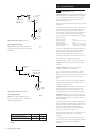
Double
Check
Valve
Heating
System
Temporary
Hose
Hose
Union
Stop
Valve
Mains Water
Supply
(Service Pipe)
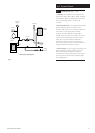
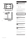
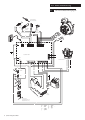
Heating
System
Pressure Pump
Reducing Valve
(if required)
Cistern
Stop
Valve
Mains Water
Supply
Filling a Sealed Water System (Method 1)
Mains Topping Up Method
NOTE: This method of filling a sealed system
may only be used if acceptable to Local Water
Undertaking
Filling a Sealed Water System (Method 2)
Cistern Filling Method
NOTE: Cistern to be supplied through a
temporary connection from a service pipe or
cold water distributing pipe
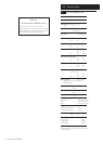
Vessel Charge Pressure (bar)
Initial System Pressure (bar)
Expansion Vessel Volume (litres)
0.5
1.0
V x 0.11
1.5
1.0
V x 0.087
Table 1
Fig. 7
Fig. 8