


28
© Baxi Heating UK Ltd 2009
9.0 Annual Servicing
9.2 Annual Servicing - Inspection
1. Ensure that the boiler is cool.
2. Ensure that the gas supply to the boiler is isolated.
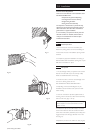
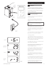
3. Operate the Reset switch (Fig. 41) to activate the
condensate pump and then repeat. This will empty most of
the condensate from the sump.9. Isolate the boiler from the
electrical supply.
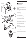
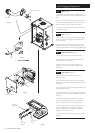
4. Undo & remove the flue sampling plug and washer. Remove
the screws retaining the boiler front panel, and lift the panel
away (Fig. 43).
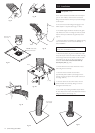
5. Remove the screw securing the PCB control box and swing
the box to the right (Fig. 43).
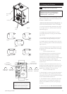
6. Disconnect the two plugs from the fan motor and remove
the sensing pipe from between the gas valve and fan outlet.
7. Remove the gas feed pipe and washers, and extract the
injector from the gas/air inlet manifold.
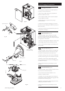
8. For ease of access disconnect the following:-
a) 2 pin plug on NTC lead
b) all wires from electrode assembly
c) all wires from spark generator
d) both wires from the overheat thermostat
e) the red and black wires connected together
9. Undo the two securing nuts and remove the spark
generator and bracket.
10. Undo the combustion panel securing nuts and remove the
special spring washers. Remove the complete fan & panel
assembly from the boiler.
11. Lay the assembly to one side. The outer insulation panel is
fitted to the rear of the combustion box panel.
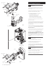
12. Clean inside the heat exchanger and examine the
condition of the fins.
13. Examine the burner, electrodes, insulation and seal,
replacing if necessary. Also check the condition of the three
insulation pieces in the rear of the heat exchanger.
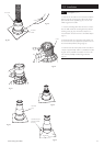
14. Disconnect the wires on the condensate pump motor and
pull off the plastic discharge pipe. Cut and remove the transit
cable tie. It is not necessary to replace this item.
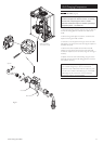
15. Squeeze the two retaining clips and turn the pump
anticlockwise to remove it. Draw it upwards from the sump.
16. Clean any debris from the sump and examine the
condition of the pump seal, replacing if necessary.
17. Reassemble in reverse order of dismantling, checking and
replacing any components as necessary. Recommission the
boiler and complete the relevant Service Interval Record
section of the Benchmark Commissioning Checklist at the rear
of this publication.
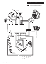
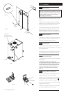
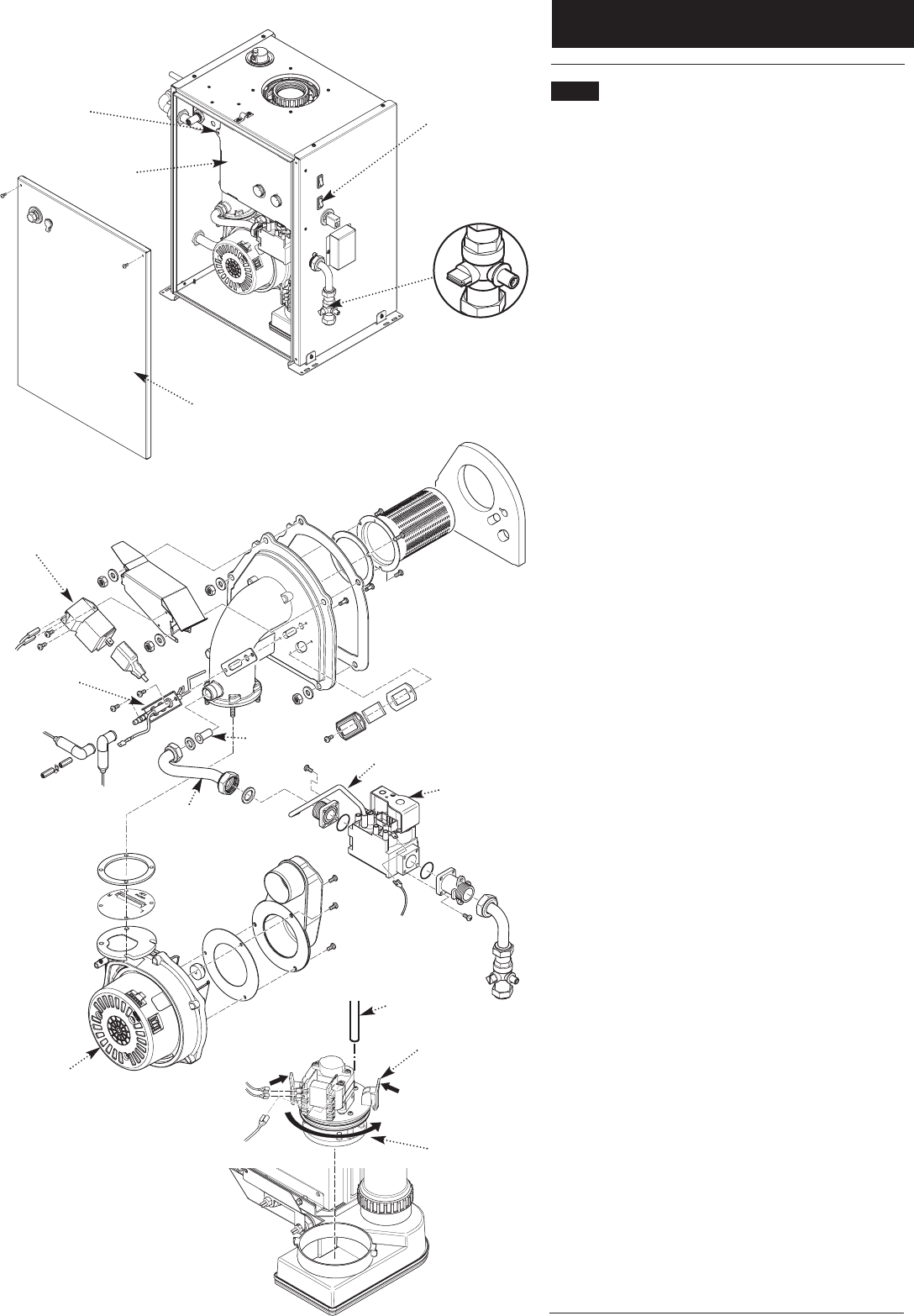
Fig. 43
PCB Control
Box
PCB Control Box
Securing Screw
Locking Clip
Condensate Pump
Discharge Pipe
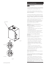
Fig. 44
Boiler Front
Panel
Spark
Generator
Electrode
Assembly
Injector
Sensing Pipe
Gas Valve
Gas Feed
Pipe
Fan
Reset Switch
Off Position