


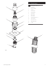
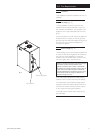

4.0 System Details
13
© Baxi Heating UK Ltd 2009
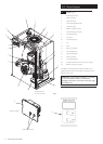
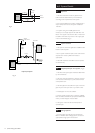
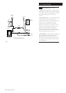
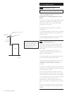
4.7 Sealed Systems (Figs. 6, 7 & 8)
1. Installation. The installation must comply with the
requirements of BS 6798 and BS EN 12828. The British
Gas publication “British Gas Specification for Domestic
Wet Central Heating Systems” should also be
consulted.
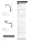
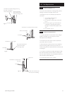
2. Pressure Relief Valve. A non-adjustable spring loaded
pressure relief valve, preset to operate at 3 bar
(45 lbf/in
2
) shall be used. It must comply with BS 6759:1
and include a manual testing device. It shall be
positioned in the flow pipe either horizontally or
vertically upwards and close to the boiler. No shut off
valves are to be placed between the boiler and the
safety valve. The valve should be installed with a
discharge pipe which permits the safe discharge of
steam and hot water such that no hazard to persons or
damage to electrical components is caused.
3. Pressure Gauge. A pressure gauge incorporating a fill
pressure indicator, covering the range 0-4 bar (60
lbf/in
2
) shall be fitted to the system. It should be
connected to the system, preferably at the same point
as the expansion vessel. Its location should be visible
from the filling point.
Air Vent
Boiler
Pump
Radiator
Circuit
Fully Pumped Sealed System
Filling
Point
Indirect
Cylinder
Return
Flow
Pressure
Gauge
Safety
Valve
Expansion
Vessel
Fig. 6