


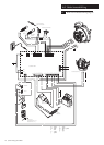
7.0 Installation
24
© Baxi Heating UK Ltd 2009
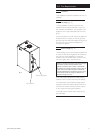
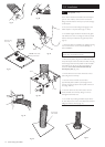
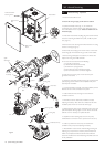
7.3 Siting the Boiler
IMPORTANT - This product should be lifted and
handled by two people. Stooping should be avoided and
protective equipment worn where necessary. Carrying
& lifting equipment should be used as required, e.g.
when installing on another floor.
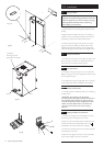
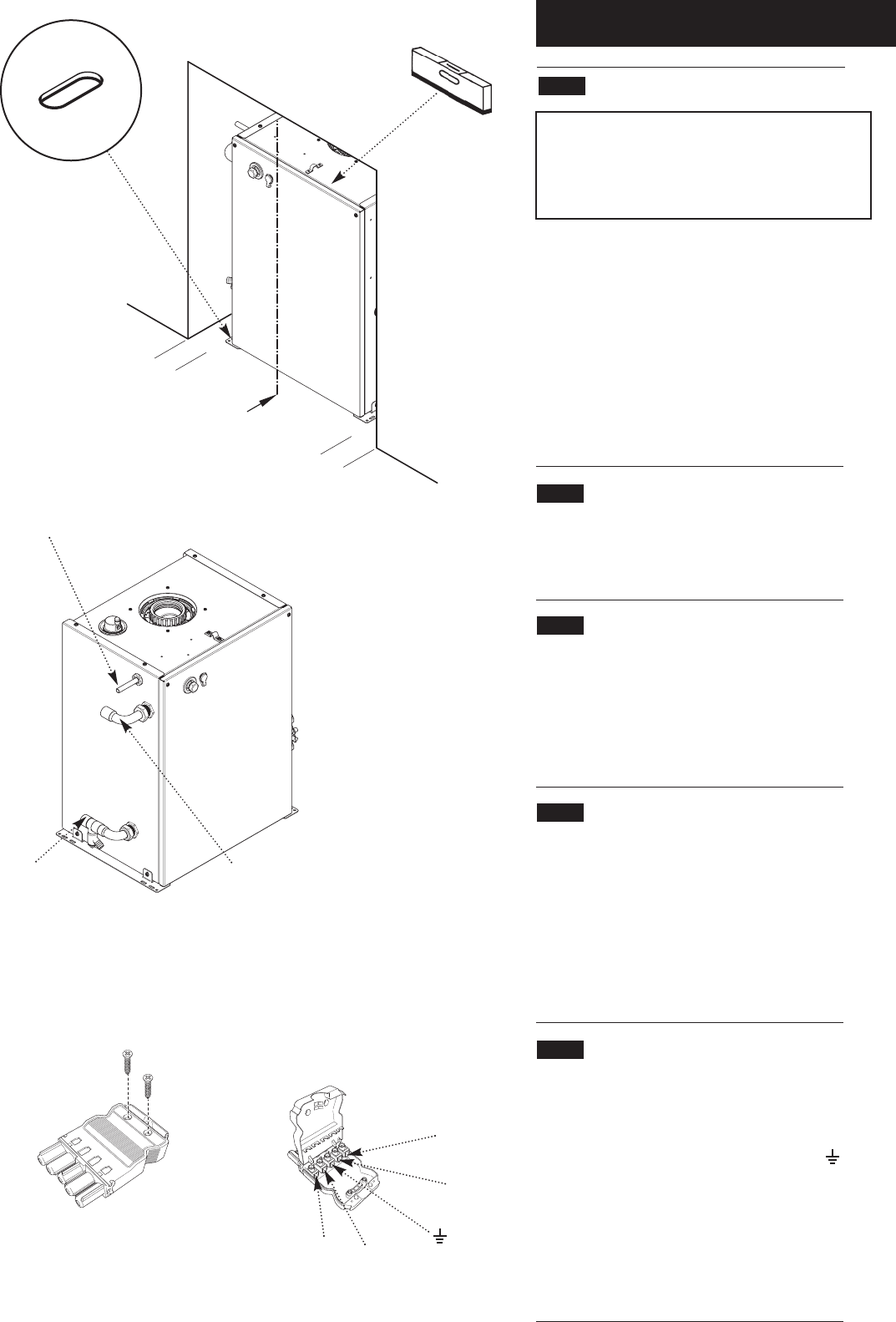
1. Lift the boiler from the packing base and place into the
opening.
2. Align the boiler centrally as far back in the opening as
possible, and ensure the distance between each side and
the opening is equal. Check that the boiler is level.
3. Mark the hearth through two of the slots in the base
(Fig. 35). Remove the boiler and drill the hearth. Insert
suitable plugs. Replace the boiler & check the alignment
within the opening. Secure the boiler with suitable screws.
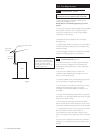
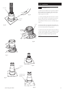
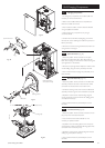
7.4 Water Connections
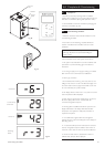
1. The boiler has one return and one flow connection. The
flow is the upper connection. It is essential the flow and
return pipes are connected correctly (Fig. 36).
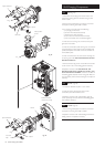
7.5 Gas Connection
1. Connection to the gas supply is a 15mm compression
fitting on the gas cock. The gas supply pipe must be routed
from the right hand side.
2. The positioning of the gas supply pipe must not restrict
the servicing of the boiler or installation of the firefront.
7.6 Electrical Connection
1. The boiler requires an electrical supply from the heating
controls system.
WARNING: The appliance must be earthed.
The input cable for the appliance should be 0.75mm
2
to
IEC Code 227 (heat resistant). The system external
controls and the boiler must be supplied by the same
isolator.
The boiler MUST NOT be connected to the
same supply as the firefront as their fuse ratings are
different.
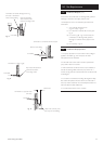
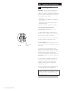
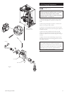
7.7 Making the Electrical Connection
1. Take the 5 pin plug from the boiler fitting kit, remove
the securing screws and hinge the cover open.
2. Route the mains inlet cable under the cable clamp and
connect Permanent Live, Neutral & Earth to 3, N &
respectively. Ensure that the Earth lead is longest.
3. Connect the switched output from the system external
control system to terminal 1.
4. Refit the cover, tighten the screws to secure the cable
and connect the plug to the one on the boiler.
Fixing Slot
Condensate
Discharge (remove
plug before connection)
Return
Flow
1
2
N
3
Fig. 35
Fig. 36
Fig. 37