


26
© Baxi Heating UK Ltd 2009
8.0 Completion & Commissioning
8.2 Commissioning the Boiler (cont.)
IMPORTANT: The combustion for this appliance has
been checked, adjusted and preset at the factory for
operation on the gas type specified on the appliance data
plate. No measurement of the combustion is necessary.
Do not adjust the air/gas ratio valve.
Having checked:
That the boiler has been installed in accordance with
these instructions.
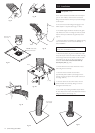
The integrity of the flue system and the flue seals, as
described in Section 7.2.
Proceed to put the boiler into operation as follows:
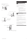
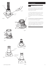
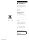
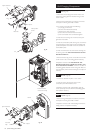
Check the Operational Gas Inlet Pressure
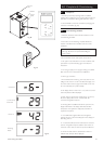
14. Set the boiler to operate at maximum rate as
described in Section 11.1.2 to 11.1.6.
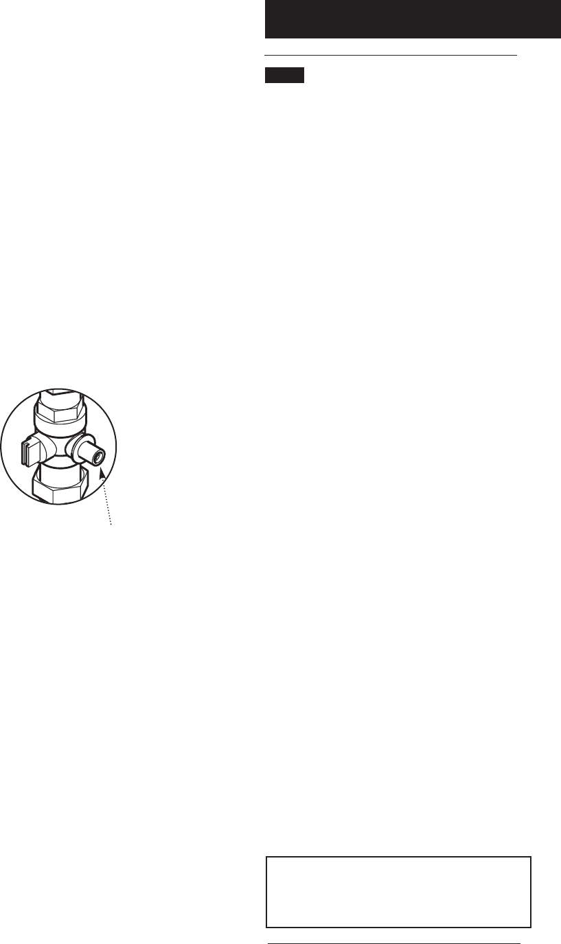
15. With the boiler operating in the maximum rate
condition check that the operational gas pressure at the
inlet gas pressure test point is 20mb (Fig. 40a).
16. Ensure that this inlet pressure can be obtained with
all other gas appliances in the property working.
Measure the Gas Rate
17. With any other appliances & pilot lights turned OFF
the gas rate can be measured. It should be between 1.55
and 1.71m
3
/h.
18. Carefully read and complete all sections of the
Benchmark Commissioning Checklist at the rear of this
publication that are relevant to the boiler and installation.
These details will be required in the event of any
warranty work. The publication must be handed to the
user for safe keeping and each subsequent regular service
visit recorded.
For IE, it is necessary to complete a “Declaration of
Conformity” to indicate compliance with I.S. 813. An
example of this is given in I.S. 813 “Domestic Gas
Installations”. This is in addition to the Benchmark
Commissioning Checklist.
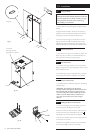
19. Disconnect the Boiler Control and fit the firefront in
accordance with the instructions supplied with it.
IMPORTANT: The loose boiler serial number label
supplied in the boiler kit must be applied to an area of
the spacer frame that is visible to the end user e.g.
lower right hand side.
Inlet Gas Pressure
Test Point
Fig. 40a