


30
© Baxi Heating UK Ltd 2009
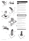
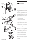
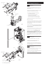
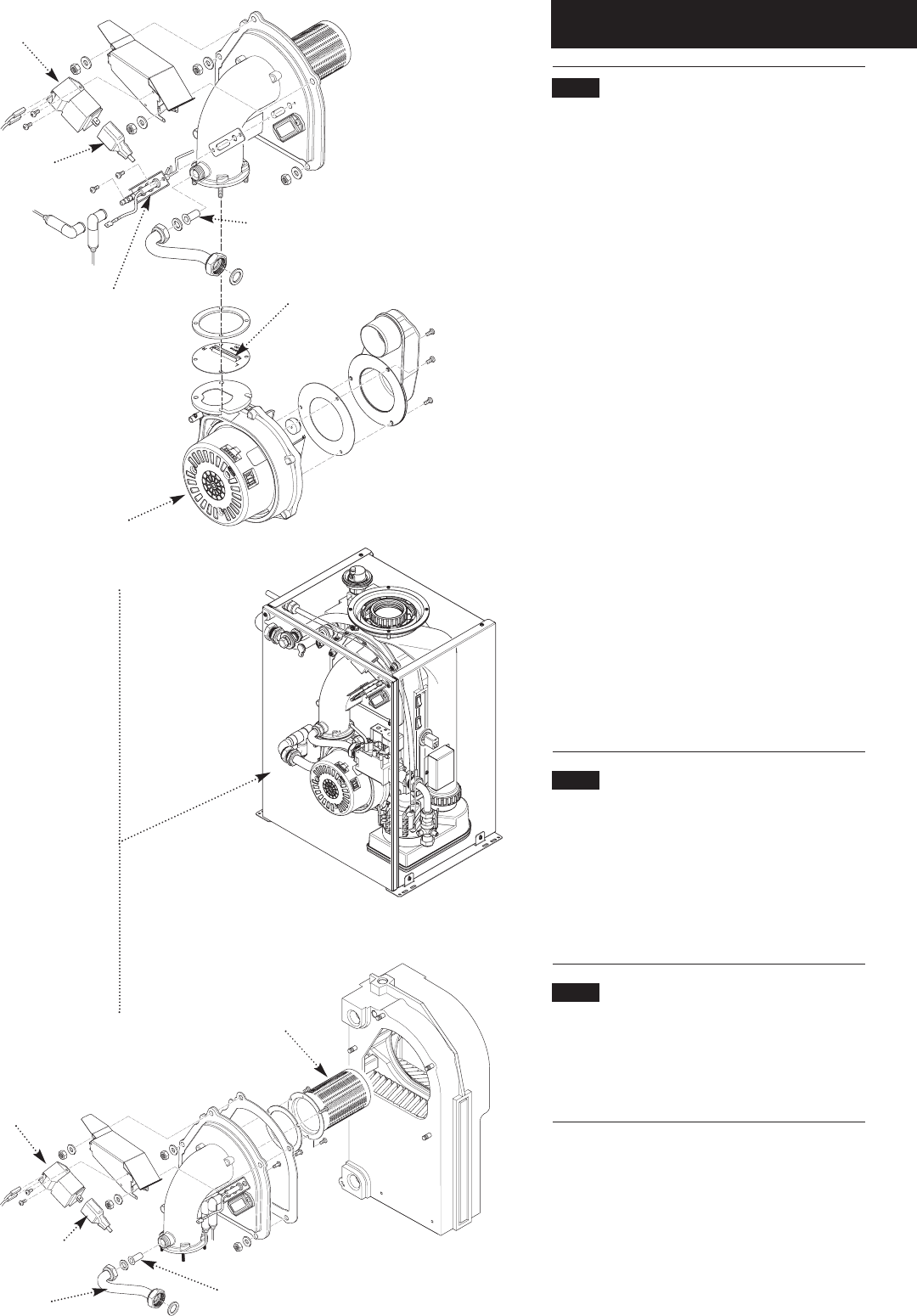
10.5 Fan (Fig. 49)
1. Disconnect the two plugs from the fan motor and
remove the sensing pipe from between the gas valve
and fan outlet.
2. Remove the gas feed pipe and washers, and extract
the injector from the gas/air inlet manifold.
3. For ease of access disconnect the following:-
a) 2 pin plug on NTC lead
b) all wires from electrode assembly
c) all wires from spark generator
d) both wires from the overheat thermostat
e) the red and black wires connected together
4. Undo the two securing nuts and remove the spark
generator and bracket.
5. Undo the combustion panel securing nuts and remove
the special spring washers. Remove the complete fan &
panel assembly from the boiler. Check the condition of
the insulation piece.
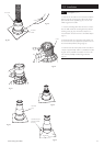
6. Undo and remove the nuts and washers securing the
fan to the gas/air inlet. NOTE THE POSITION OF THE
RESTRICTOR PLATE !
7. Remove the securing screws and transfer the fan inlet
to the new fan. Use a new sealing gasket if necessary.
8. Replace in reverse order. ENSURE THAT THE
RESTRICTOR PLATE IS CORRECTLY FITTED ! THE
SLOT MUST BE TO THE REAR. Check the condition of
the sealing gaskets between the fan and gas/air inlet and
the combustion panel and heat exchanger and replace if
necessary.
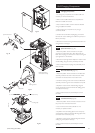
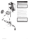
10.6 Burner (Fig. 50)
1. Proceed as described in points 1. to 5. above.
2. Undo the screws securing the burner to the
combustion panel. Remove the burner.
3. Replace in reverse order of dismantling, using the
screws previously removed. Examine the sealing gasket
and replace if necessary.
10.7 Injector (Fig. 50)
1. Remove the gas feed pipe and washers, and extract
the injector from the gas/air inlet manifold.
2. Replace in reverse order of dismantling. Examine the
sealing washers and replace if necessary.
10.0 Changing Components
PCB Control Box
removed for clarity
Burner
Injector
Injector
Spark Generator
Plug
Fan
Spark Generator
Plug
Electrode
Fig. 49
Fig. 50
Note position
of Slot
Gas Feed
Pipe