29
© Baxi Heating UK Ltd 2009
10.0 Changing Components
10.1 Changing Components
1. To change any components on the back boiler it is
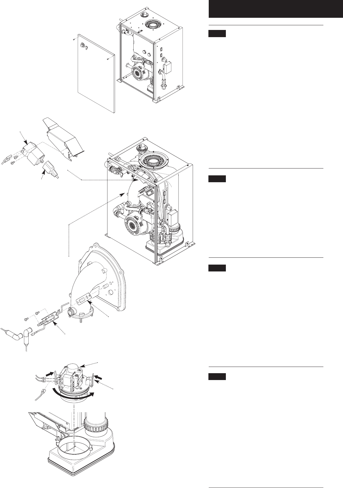
necessary to remove the firefront.
2. Refer to the Installer Guide that accompanies the
firefront for details of removal.
3. Ensure that the boiler is cool and that the electrical
and gas supplies are isolated.
4. After changing any components carry out gas
soundness checks.
5. Undo & remove the flue sampling plug and washer.
Remove the screws retaining the boiler front panel, and
lift the panel away.
6. Remove the screw securing the PCB control box and
swing the box to the right.
10.2 Spark Generator (Fig. 46)
1. Note the position of the two leads on the spark
generator and disconnect them. Also disconnect the
earth wire and plug, and remove the screws securing the
spark generator to the bracket.
2. Remove the spark generator. Replace in reverse order
of dismantling, using the screws previously removed.
3. Ensure that the leads and plug are pushed fully on to
their terminals.
10.3 Electrode Assembly (Fig. 47)
1. Note the position of the two leads on the electrode
assembly and disconnect them. Disconnect the in-line
connection on the black wire and the earth wire.
2. Undo the securing screws and remove the electrode
assembly and earth tag from the combustion box panel.
3. Replace in reverse order of dismantling, using the
screws previously removed. Examine the sealing gasket
and replace if necessary.
4. Ensure that the leads are pushed fully on to their
terminals.
10.4 Condensate Pump (Fig.48)
1. Note the position of the two leads and earth wire on
the pump motor and disconnect them.
2. Cut and remove the transit cable tie. It is not
necessary to replace this item.
3. Squeeze in the two locking clips and turn the pump
anti-clockwise. Pull the condensate discharge pipe off its
connection and remove the pump.
4. Replace in reverse order of dismantling. Examine the
sealing ring and replace if necessary.
5. Ensure that the leads are pushed fully on to their
terminals.
PCB Control Box
removed for clarity
Spark Generator
Plug
Electrode
Sealing Gasket
Locking Clip
Condensate Pump
Fig. 45
Fig. 46
Fig. 47
Fig. 48


