


54
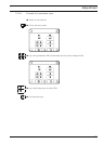
14 Stromlaufpläne
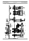
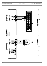
8 Circuit diagrams
8
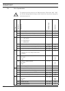
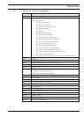
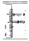
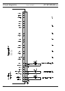
.01 Reference list for circuit diagrams 91-191 525-95
Circuit diagrams
A1 Controller Quick P 320MS
A2 Control panel (BDF T1)
A3 Keyboard
A14 Sewing head identifi cation (OTE)
H1 Sewing lamp
M1 Sewing motor
M3 Stepping motor fullness adjustment (SM1)
Q1 Main switch
S6 Knee switch (program switching)
S17 Pedal speed control unit
S18 Sychronizer PD3
X1 Mains plug
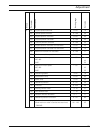
X1A RS232 – interface 1 Control panel BDF T1
X1B VSS OTE (Sewing head identifi cation)
X3 Incremental transmitter (control unit)
XR3 Incremental transmitter (sewing motor)
XS3 Sychronizer PD3
X4B Stepping motor fullness (SM1)
X5 Inputs
X8 Sewing motor
X11A CAN interface (Keyboard)
X11B Pedal speed control unit
X13 Outputs
X21 Stepping motor fullness (SM1) )
X22 Keyboard
X36 Knee switch (program switching)
X46 Initiator reference (SM1)
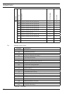
X51 Y1 -910/.. Automatic presser foot lift
X52 Y2 -900/.. Thread trimmer
X55 Y5 -911/.. Backtacking unit
Y1 -910/.. Automatic presser foot lift
Y2 -900/.. Thread trimmer
Y5 -911/.. Backtacking unit