


Chapter 3: S-PCON-U (Power Connector)
Intelli-M Hardware Installation And Reference Guide
23
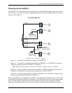
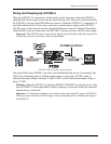
Wiring And Powering Up S-PCON-U
When the S-PCON-U is connected to a PoE enabled switch, electronics inside the S-PCON-U
signal the PoE switch to place power onto the input ethernet cable. This power is then directed by
the S-PCON-U onto the output RJ45 Ethernet connector. When the S-PCON-U is connected to a
non-PoE enabled switch it is necessary to provide an external power supply to the S-PCON-U.
This DC power is then directed onto the output RJ45 Ethernet connector. If both a PoE enabled
switch and DC power are connected to the S-PCON-U, priority is given to the DC power supply.
Important: The S-PCON-U device and its Power Supply must be installed within the protected area
(locked area) of the access facility to meet UL requirements.
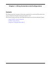
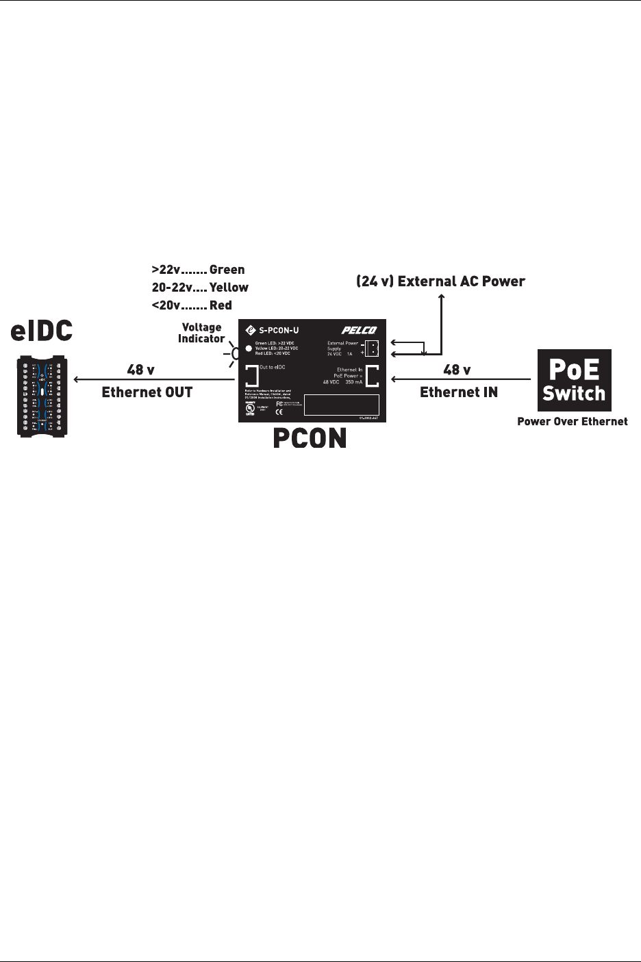
S-PCON-U Wiring and Powering up Diagram
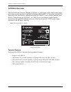
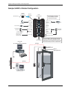
The output LED on the S-PCON-U provides visual feedback that the device is functioning. The
LED can be illuminated green to indicate output voltage is greater than 24 VDC, amber to
indicate that output voltage is between 22 and 24 VDC, or red to indicate that output voltage is
below 22 VDC.
Warning: When the S-PCON-U is operating DO NOT CONNECT any ethernet device other
than an S-EIDC-U to the output RJ45 connector. Damage to electronics inside the connected
ethernet device could result.
Important: It is important to maintain correct polarity when connecting a DC supply to S-PCON-U.
Check for proper connection of the DC supply on the provided plug prior to connecting the supply to
the S-PCON-U.
This device complies with part 15 of the FCC rules.
Operation is subject to the following two conditions: (1) This
device may not cause harmful interference, and (2) This
device must accept any interference received, including
interference that may cause undesired operation.
22.9- 24VDC@1A
@
@