


Chapter 2: S-EIDC-U (ethernet Integrated Door Controller)
14
Intelli-M Hardware Installation And Reference Guide
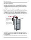
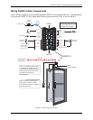
The steps necessary to wire an S-EIDC-U for a single door are as follows:
Step 1: Connect magnetic lock or door strike. Refer to the illustration above.
The following information may be pertinent when dealing with locks or door strikes:
•A magnetic lock or door strike can be powered by the eIDC (12 VDC @ 450 mA or less).
This is a shared load.
• The two Open Collector outputs “OC1” and “OC2” (Output 1 and Output 2) provide a maxi-
mum of 12 VDC @ 450 mA combined.
• “OC1” and “OC2” each have their own “-” terminal but share a “+” terminal.
• “OC1” and “OC2” are software configurable “E” (energized) or “DE” (de-energized).
•
Magnetic locks can be powered by the Open Collector output if it draws less than 450 mA. If
it draws more than 450 mA, then it must be wired to the form C relay (5A @ 30 VDC) labeled
“NC” and “NO” and powered externally.
• Relay (Output 3) has separate terminals for “C” (Common), “NO” (Normally Open), and
“NC” (Normally Closed) but the software designation must match for proper status reporting.
Important: To meet UL requirements, listed panic hardware must be used to allow emergency exit
from the protected area.
Step 2: Wire the status, shunt, and exit inputs.
Keep in mind the following points:
• Input devices can be wired to S-EIDC-U Inputs (IN) 1-4.
• “NO” or “NC” is software configurable with Inputs 1-4.
• “EOLR” (End Of Line Resistance) supervision is software selectable, and is supported with 1k
ohm resistors.
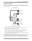
Step 3: Wire the readers.
Keep in mind the following points:
• Reader IN (CRI) and Reader OUT (CRO) are internally configured each having their own
Data 0 (CR-), Data 1 (CR+), DC+, and DC-.
• “DC1-” has a maximum load of 250 mA; “DC2-” has a maximum load of 250 mA.
• The sum of all 4 open collectors (OC1 + OC2 + DC1 + DC2) must not exceed 750 mA.
• There is a single terminal for optional Reader LED control and optional Buzzer control.
• Only Readers can be wired to the Reader’s Data 0 (CR-), and Data 1 (CR+) terminals.