27
4.3.5 Configuration (continued)
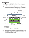
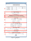
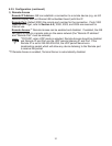
Below are the definitions of terms used in the Configuration page.
A) Configuration/Device Setup
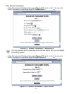
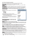
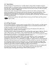
Clicking on the No. 1, 2, 3, 4 or 5 allows you to modify the Sensor Parameters (see
Section 4.3.6 for more details).
B) Real Time Clock
RTC Date and Time: The formats are mm/dd/yyyy and hh:mm:ss. The exact formats
are required otherwise an error message will appear in the Title box. Note: time is
military time/24 hour based.
Adjust RTC Only: If checked, the clock will be updated and nothing else, provided
that “Activation” is set to “Status/RTC/Alarm”. To verify the clock, set the “Activation”
to “Configuration”, click Update button, then set “Activation” to “Status/RTC/Alarm”
and click Update button one more time.
Time Stamp: If checked, the Temperature values will be stamped with time and date
using Port 1000 (HTTPget program must be used, see Section 4.5.1).
Secured Applet: If checked, the LOGIN password is required to open “Read Sensor”
and “Chart” pages.
C) Flash Card Size: Reports the Flash Card density and if it is already recorded, how
many locations are filled.
0-Megabytes: Flash Card is not installed or a bad Flash Card
2-Megabytes, 4-Megabytes, 8-Megabytes: available sizes of Flash Cards.
D) Flash Card Message: Describes RTC setup, listed in the previous 4 scenarios.
Flash Card Module Malfunctional Open Sensor
Flash Card Standby Flash Card Recording Stopped
Flash Card Pre-Recorded Flash Card Recording Complete
Flash Card Recording On Wait Reading Flash
Flash Card Module Not Initialized Recording Initialized
Flash Card Corrupt Initialization
If the battery is not connected or the voltage is low, the statement “Low Battery” will
be added to the above statements. You may also see a statement “Archive Busy” if
another client is busy receiving archive data. In this case, refrain from activating the
applet, instead keep clicking the Update button and make sure “Activation” is set to
“Status/RTC/Alarm” until the “Archive Busy” statement is no longer displayed.
E) Alarm Setup: There are two alarms which can be assigned to Temperature 1
Temperature 2 (one alarm to each variable). Selection of Input 1 or Input 2 and
Setpoint High (SP_H) or Setpoint Low (SP_L).
Temperature 1
and Temperature 2: Disable, Low, High, High/Low
Disable: Alarm is disabled (no alarm function)
Low: Alarm is enabled only with Low setpoint
High: Alarm is enabled only with High setpoint
High/Low: Alarm is enabled only with High and Low setpoints


