


Optional Equipment (for qualified installers only) 59
© Travis Industries 4070201 100-01182_002
Duct Installation Instructions
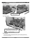
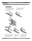
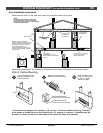
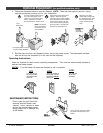
Determine the route for the heat duct using the illustration below as a guide.
Use 10” x 3-1/4” wall stack
(duct) when passing
through tight areas.
20’ Maximum
Length
Duct Adapter
(6” Round to 10” x 3-1/4” -
included with the power heat
vent kit)
Blower Box
0” Clearance to
Combustibles
Co-Axial Vent
(for intake air
and exhaust)
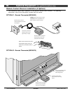
NOTE:
Air flow through the duct is affected by
length and number of bends. Keep the
length and number of bends to the minimum
to maximize performance.
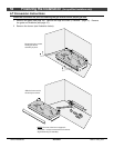
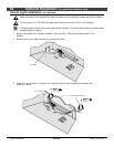
When the duct penetrates the
fireplace enclosure vertically and the
top of the enclosure is within 36” of
the top of the fireplace, a firestop
spacer that maintains a 1/2”
clearance between all sides of the
duct and any combustible material
must be used.
1/2”
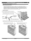
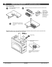
Attach the blower box to the framing or floorboards of the home following the instructions below.
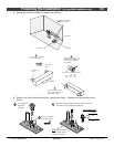
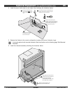
Wall or Ceiling Mounting
b
Attach the wall mounting
brackets to the blower box.
Mount the bracket to
these holes for 2 x 4 walls
Mount the bracket to
these holes for 2 x 6 walls
Cut a hole between wall
framing members for the
blower assembly.
a
5-1/4"
16"*
c
Slide the blower, with
wires, into the hole cut
in step "a". Attach
with four screws.
* This blower was designed for framing on 16" centers. Construct additional framing if needed.
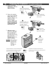
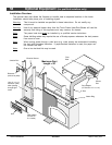
If the blower is installed prior to the drywall only a 14" opening is required. If installed after the
drywall is in place, the drywall to the sides of the blower will need to be patched.