


Installation (for qualified installers only) 23
© Travis Industries 4060907 100-01182
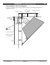
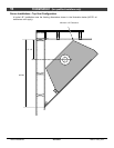
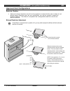
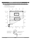
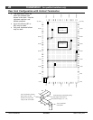
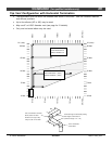
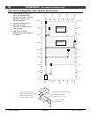
Approved Vent Configurations
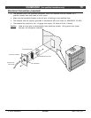
Restrictor Position
• Intake and exhaust restrictors are built into the appliance to adjust the flow rate of intake air and
exhaust gases. Depending upon the vent configuration, you may be required to adjust the
restrictor positions. The charts for acceptable vent configurations detail the correct vent
restrictor positions.
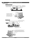
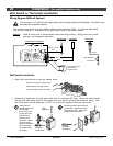
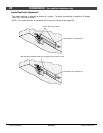
Exhaust Restrictor Adjustment
If the diffuser is required to be in position # 2, you may wish to adjust the diffuser while the exhaust
restrictor is removed.
Loosen these four screws
on the exhaust restrictor.
Slide the restrictor to the correct
restrictor position (see the illustration
below). The rear screws indicate
restrictor position. In this example, the
restrictor is set in position # 3. Tighten
the screws to secure the restrictor.
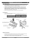
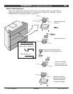
NOTE: If using position 4, 5, or 6, you
will need to remove the forward
screws. These screws are then re-
inserted into the back holes exposed
while sliding the restrictor.
(closed) #6
# 5
# 4
# 3
# 2
(open - stock position) # 1
Back of Firebox
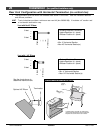
Back Wall of Firebox
Firebox Roof